Configure a Current-Voltage sensor
- Lalanne Laurent
- Marc Proe
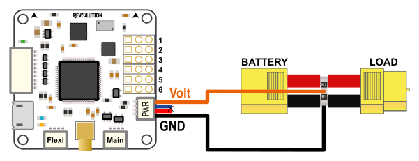
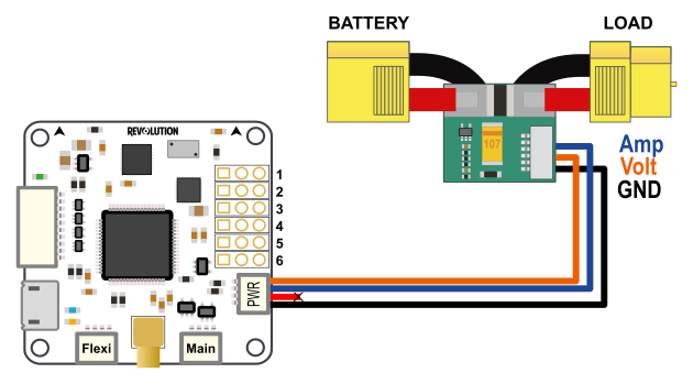
Hardware connections
| JST connector | Connector pin (board) | Description | AttoPilot pin (sensor) |
|---|---|---|---|
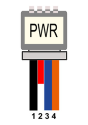 | 1 | GND | GND |
| 2 | Vcc | Not used | |
| 3 | Current Input | I | |
| 4 | Voltage Input | V |
Voltage input
Any sensor can be used as long as the input voltage to Revo's Sensor Port pins does not exceed 3.3V. Higher values can damage board's CPU!
Basic voltage sensor
A basic voltage divider can be used, two resistors connected between ground and + from battery.
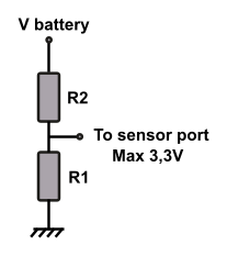
For a 4S battery (16.8Volts) the following values can be used:
R1: 2,2KOhms and R2: 10KOhms
With Vbattery = 16.8V, Vout = (16.8 * 2.2) / (10 + 2.2) = 3,03V
Disable TIME alarm
If you use this simple voltage sensor alone, you need to disable the TIME alarm.
This alarm is based on energy consumed that cannot be computed without current sensor.
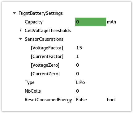
Go to UavoBrowser > FlightBatterySettings and set the Capacity to 0
Current / Voltage sensor
Here is a list of common sensors that can be used :
| Module | Type | Sensitivity | VoltageFactor | CurrentFactor | VoltageZero | CurrentZero | Notes |
|---|---|---|---|---|---|---|---|
| Attopilot | 50V/180A | 63.69mV/V, 18.30mV/A | 15.701 | 54.645 | 0 | 0 | |
| Attopilot | 50V/90A | 63.69mV/V 36.60mV/A | 15.701 | 27.322 | 0 | 0 | Same as RCTIMER 90A current sensor |
| Attopilot | 13.6V/45A | 242.3mV/V 73.20mV/A | 4.127 | 13.661 | 0 | 0 | |
| Hobbyking | 50V/120A | 97.465 mV/V 31.699mV/A | 10.26 | 31.5467 | 0 | 0 | HK Pilot Power VI Module |
For custom sensor see the Calculate SensorCalibration values section.
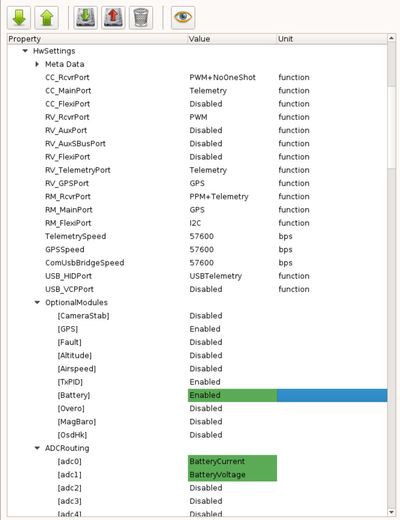
Hardware settings
The first thing to do is to configure the hardware settings:
1 - Connect the board to your computer and got to the System tab in your GCS
2 - Browse the first part (Settings) and find the HwSettings UAVObject
3 - Enable the Battery module : OptionalModules > Battery > Enable
4 - Set the analog input pins for voltage and current :
- ADCRouting > adc0 > BatteryCurrent
- ADCRouting > adc1 > BatteryVoltage
5 - Save changes, click Upload button : 
6 - Reboot your board: disconnect all power sources and reconnect to your computer.
Here is the adc mapping for various boards:
| Board | adc0 | adc1 | adc2 | adc3 | adc4 | adc5 | adc6 |
|---|---|---|---|---|---|---|---|
| Revolution | PWR port pin 3 | PWR port pin 4 | Output port out 3 | Output port | Output_port | Output port | internal |
| Sparky2 | PWR port pin 3 | PWR port pin 4 | PWR port pin2 | Output port | Output port | Output_port | Output port |
| RevoNano | FlexiIO | FlexiIO pin 5 | FlexiIO pin 6 | FlexiIO pin 7 | FlexiIO pin 8 | Output_port out 5 | Output port out 6 |
FlexiIO refers to the receiver port
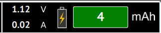
Calibrate sensor
Now connect the battery to the battery sensor, if changes are done and battery module enabled you can see the display on PFD:
But values displayed are not accurate, we need to calibrate sensor!
Calculate SensorCalibration values
To configure the battery monitor, you need to calculate the SensorCalibration values.
For example, the documentation for Attopilot current sensor specifies the following information for each sensor type:
In order to use 50V/90A you'll have to do the following:
Convert everything to Volt, so Volt/Volt and Volt/Amp:
63.69mV/V / 1000 = 0.06369 V/V
36.60mV/A / 1000 = 0.0366 V/A
Then calculate the values to insert in Voltage and Current Factors:
VoltageFactor = 1 / 0.06369 = 15.701
CurrentFactor = 1 / 0.0366 = 27.322
Those factors are start values that can be adjusted later from readings, generally sensor's sensitivity are not so accurate.
| Sensor type | Voltage sensitivity | Current sensitivity |
|---|---|---|
| 50V/180A | 63.69mV/Volt | 18.30mV / Amp |
| 50V/90A | 63.69mV/Volt | 36.60mV / Amp |
| 13.6V/45A | 242.3mV/Volt | 73.20mV / Amp |
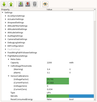
Setting FlightBatterySettings Properties
1 - Connect the board to your computer and got to the System tab in your GCS
2 - Browse the first part (Settings) and find the FlightBatterySettings UAVObject
3 - Set the VoltageFactor and CurrentFactor as in the previous section.
4 - Set the cell Capacity if you want a warning to be issued when there are less than 2 minutes of flight time available; otherwise, set to 0.
5 - Set NbCells with the number of cells in series (2 for 2S, 3 for 3S, 3 for 3S2P)
6 - Set the Warning and Alarm thresholds if you would like a warning or critical alarm to be issued when going under the values that you specify.
7 - Save changes, click Upload button :
Offset
Sometimes sensor are not accurate with small readings, especially for current. A CurrentZero setting can be set: without any load change this value to obtain a 0amps display.