Revolution Configuration
- Paul Jewell
- Lalanne Laurent
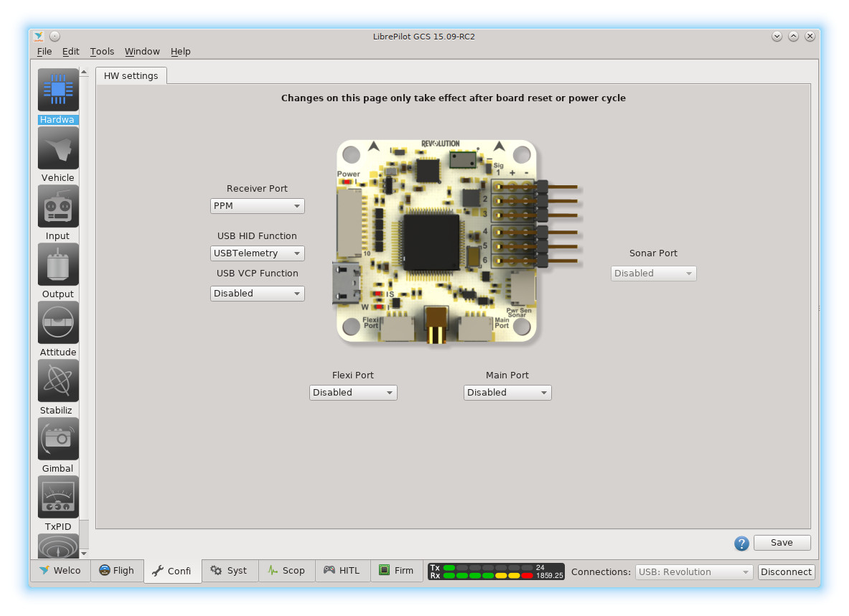
When the Revolution flight controller is plugged into the GCS, the Hardware Configuration screen displays the ports available on the controller to allow them to be set according to use. The board can be mounted in any configuration on the airframe, and the orientation relative to the airframe configured such that the flight controller knows which way it is facing.
Receiver Port
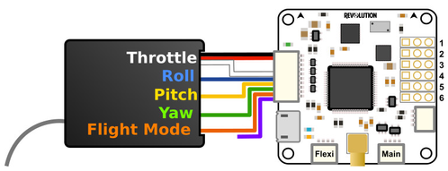
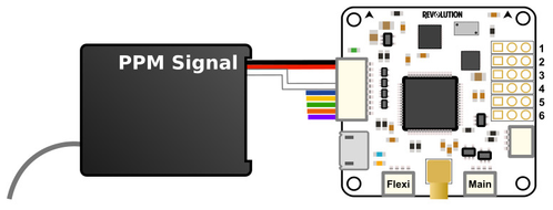
Also called FlexiIO. This port can be used to interface with the RC receiver using PWM or PPM protocols, some pins can also be used for Led outputs, Motor outputs or DTR pin for OSD programming.
Multiple combinations are possible: PWM, PPM, PPM+PWM, PPM+Outputs, PPM+Telemetry, PPM+DebugConsole, PPM+ComBridge, PPM+MSP, PPM+MAVLink, PPM+GPS, Outputs, Telemetry, DebugConsole, ComBridge, MSP, MAVLink or GPS.
Serial function can be used with Telemetry or DebugConsole, ComBridge, MSP, MAVLink, GPS.
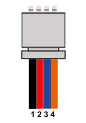
FlexiIO pinOut / Functions
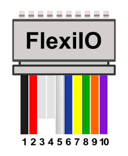
Pin | Color | PWM input Function | PPM input Function | PPM +Serial Function | PPM+Outputs Function | Outputs Function | Serial Function |
|---|---|---|---|---|---|---|---|
1 | Black | Ground | Ground | Ground | Ground | Ground | Ground |
2 | Red | Vcc | Vcc | Vcc | Vcc | Vcc | Vcc |
3 | FlexiIO_Pin4 and FlexiIO_Pin3 can be used for WS2811_Led output | ||||||
4 | |||||||
5 | White | PWM Input 1 | PPM Input ch1-12 | PPM Input ch1-12 | PPM Input ch1-12 | PWM Output 12 |
|
6 | Blue | PWM Input 2 |
|
| PWM Output 7 | PWM Output 7 |
|
7 | Yellow | PWM Input 3 |
| Telemetry TX | PWM Output 8 | PWM Output 8 | Telemetry TX |
8 | Green | PWM Input 4 |
| Telemetry RX | PWM Output 9 | PWM Output 9 | Telemetry RX |
9 | Orange | PWM Input 5 |
|
| PWM Output 10 | PWM Output 10 |
|
10 | Violet | PWM Input 6 |
|
| PWM Output 11 | PWM Output 11 |
|
Flexi Port
Can be disabled, or connected to one of the following::Telemetry, GPS, I2C, DSM, EX.Bus, HoTT, SRXL, IBus, DebugConsole, ComBridge, MSP or MAVLink.
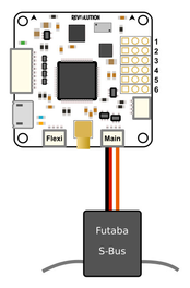
Main Port
Can also be left disabled, or connected to Telemetry, GPS, S.Bus, DSM, DebugConsole, MSP or MAVLink.
With DSM, this means the flight controller can work directly with a Spektrum satellite receiver.
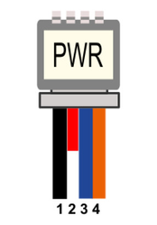
MainPort / FlexiPort pinOut
| Color | Pin | Electrical limits | Serial function | I2C function | RcInput functions S.Bus, DSM, etc... |
|---|---|---|---|---|---|
| Black | 1 | GND | GND | GND | GND |
| Red | 2 | 4.8V - 10V | PWR Out (VCC Unregulated) | PWR Out (VCC Unregulated) | PWR Out (VCC Unregulated) |
| Blue | 3 | 3.3V | TX | SCL | |
| Orange | 4 | 3.3V (5V Tolerant) | RX | SDA | TX (Signal input) |
Power Port
| JST connector | Connector pin (board) | Description | AttoPilot pin (sensor) |
|---|---|---|---|
 | 1 | GND | GND |
| 2 | Vcc | Not used | |
| 3 | Current Input | I | |
| 4 | Voltage Input | V |
See the Configure a Current-Voltage sensor page for more details.
Voltage input
Any sensor can be used as long as the input voltage to Revo's Sensor Port pins does not exceed 3.3V. Higher values can damage board's CPU!
Normal Revolution board has ESD chips that prevent for over voltage.
Sonar Port
For future implementation of a sonar function.
USB HID Function
Configurable for use as Telemetry over the USB port
USB VCP Function
Use
Based on your planned configuration, set each of the ports to the correct interface, then click "Save" in the bottom right hand corner. If you make changes, then try to move away from this page without saving the changes, you will be presented with a confirmation dialog box confirming you intended to move away without saving.
Hardware configuration changes
Any Hardware configuration changes need a reboot, this mean disconnect USB cable and remove external power before connecting again.