CC Hardware Configuration
- Paul Jewell
- Lalanne Laurent
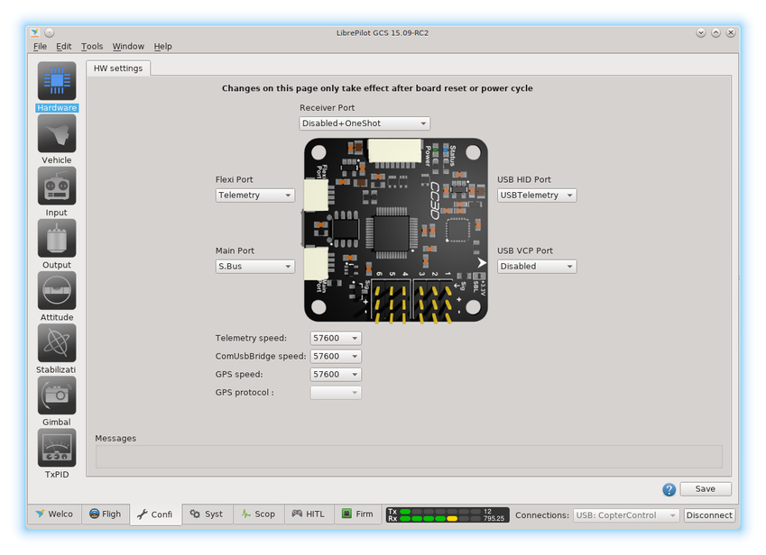
When the CC3D flight controller is plugged into the GCS, the Hardware Configuration screen displays the ports available on the controller to allow them to be set according to use. The board can be mounted in any configuration on the airframe, and the orientation relative to the airframe configured such that the flight controller knows which way it is facing.
Ports
CopterControl, CC3D and Atom have 4 ports.
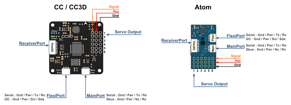
Servo Output 1-6: These are the PWM outputs that go to servos or ESCs. Power is typically applied through these headers from only one of the ESCs. The positive (Vcc) and negative (Gnd) pins are indicated on this diagram and the board.
Servo output pin layout isOutside –> groundMiddle –> 5V - 15VInside –> signal
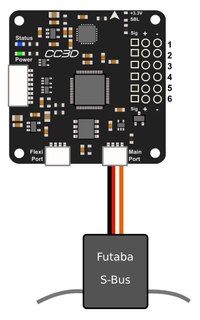
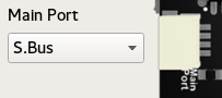
MainPort: JST-SH 4-pin. This is a serial USART whose baud rate can be adjusted through the GCS. Optionally Futaba S.Bus receiver, Spektrum/JR satellite receiver or GPS can be mapped to the MainPort. Default configuration is Telemetry for connecting an RF modem.
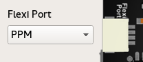
FlexiPort: JST-SH 4-pin. The function of this port also depends on the configuration and can be configured for I2C or Serial. The default configuration doesn’t use this port but it can be used for Telemetry, GPS, Spektrum satellite receivers (all working), and other I2C peripherals (under development).
ReceiverPort : JST-SH 8-pin. The receiver port can act as an input or output port depending on the configuration which is set in the Hardware Settings. Configuring the receiver port as an output port allows the user to assign more output channels then the 6 standard servo outputs.
ReceiverPort use depends on the type of RC receiver in use, and whether OneShot125 or PWMSync output is desired:
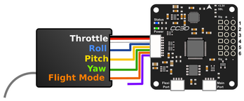
- PWM
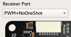
- PWM+NoOneShot should be used with a normal PWM type receiver. The 6 rightmost wires of the receiver port carry the signal for each channel individually.
- PWM+NoOneShot should be used with a normal PWM type receiver. The 6 rightmost wires of the receiver port carry the signal for each channel individually.
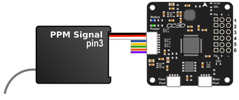
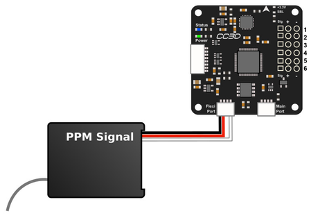
- PPM - Pin 3 (For a Multirotor, please use the PPM_PIN8+OneShot described bellow, this allow PWMSync and OneShot)
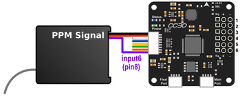
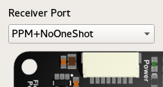
- PPM+NoOneShot is used with modern PPM type receivers, that combine the control signal to one wire.
The PPM stream should be sent to the first input through the white wire connected to CC ReceiverPort wire/pin 3.
For a PPM receiver, only one pin is used for signal - the remaining wires connected to CC ReceiverPort wires 4-8 are left unused. - PPM+PWM+NoOneShot combines the two modes above, wire/pin 3 is used for PPM and the rest, wires/pins 4-8 are used as PWM inputs.
- PPM+Outputs+NoOneShot enables PPM input in ReceiverPort wire/pin 3, and PWM output in wires/pins 5-8. These work as output channels 7-10.
- PPM+NoOneShot is used with modern PPM type receivers, that combine the control signal to one wire.
- PPM - Pin 8
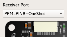
- PPM_PIN8+OneShot is a prefered input mode, where PPM input wire is moved from previous ReceiverPort pin 3 to pin 8 to allow PWMSync and OneShot125 to be used as ESC output modes.
See PWM, PWMSync, Oneshot Output page for more details.
- PPM_PIN8+OneShot is a prefered input mode, where PPM input wire is moved from previous ReceiverPort pin 3 to pin 8 to allow PWMSync and OneShot125 to be used as ESC output modes.
- RECEIVER PORT AS OUTPUTS
- Outputs+OneShot makes ReceiverPort pins 5-8 work as output channels 7-10. ReceiverPort pins 3 and 4 are unused. This and the Disabled option can be used if the control communication is via a spektrum satellite receiver or directly through telemetry.
- Outputs+OneShot makes ReceiverPort pins 5-8 work as output channels 7-10. ReceiverPort pins 3 and 4 are unused. This and the Disabled option can be used if the control communication is via a spektrum satellite receiver or directly through telemetry.
- DISABLING
- Disabled+OneShot basically disables the ReceiverPort.
- Disabled+OneShot basically disables the ReceiverPort.
Default settings
By default for a Multirotor, the Vehicle Setup Wizard will set receiver port as PPM_PIN8+OneShot when PPM type receiver is selected.
- PWM
Receiver Port
 |  |  |
| PWM input, one wire per channel | PPM input, pin3. PPM-NoOneShot | PPM input, pin8. PPM-OneShot compatible |
|
|
|
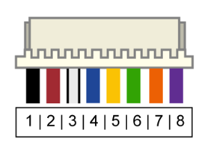
| Color | Function | JST-SH Pin | ReceiverPort pin | |
|---|---|---|---|---|
| Black | Ground | 1 | 1 |
| Red | Power to RC RX (VCC Unregulated) 4.8V - 15V | 2 | 1 | |
| White | PWM Signal 1 or combined PPM (NoOneShot) | 3 | 1 | |
| Blue | PWM Signal 2 | 4 | 2 | |
| Yellow | PWM Signal 3 or PWM Output channel 7 | 5 | 3 | |
| Green | PWM Signal 4 or PWM Output channel 8 | 6 | 4 | |
| Orange | PWM Signal 5 or PWM Output channel 9 | 7 | 5 | |
| Purple | PWM Signal 6 or PWM Output channel 10 or combined PPM (OneShot compatible) | 8 | 6 |
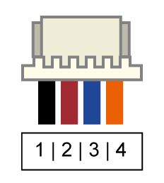
MainPort and FlexiPort serial cable pinout
 | | |
| JST connector | PPM input on FlexiPort | SBus on Mainport |
|
|
Colour | JST-SH Pin | Voltage | Serial Function | I2C Function | PPM(flexi), S.Bus, DSM, Srxl, etc... |
|---|---|---|---|---|---|
| Black | 1 | GND | GND | GND | GND |
| Red | 2 | 4.8V - 15V | PWR Out (VCC Unregulated) | PWR Out (VCC Unregulated) | PWR Out (VCC Unregulated) |
| Blue | 3 | 3.3V | TX | SCL | |
| Orange | 4 | 3.3V (5V Tolerant) | RX | SDA | TX (Signal) |
Caution
The Spektrum adapter should only be powered by 3.3V, a step down adapter must be used. See the Setup a Spektrum Satellite page.
Receiver PWM connection
Caution
The PWR Out voltage is dependent on the CC supplied voltage. Verify that you use the correct voltage for your S.BUS receiver.
For Futaba and Hitec
Channel 1 | AILERON or ROLL | White | Signal 1 |
Channel 2 | ELEV or PITCH | Blue | Signal 2 |
Channel 3 | THROTTLE | Yellow | Signal 3 |
Channel 4 | RUDDER | Green | Signal 4 |
Channel 5 | GEAR - Flight mode | Orange | Signal 5 |
Channel 6 | AUX1 | Purple | Signal 6 |
For JR and Spektrum
Channel 1 | THROTTLE | White | Signal 1 |
Channel 2 | AILERON or ROLL | Blue | Signal 2 |
Channel 3 | ELEV or PITCH | Yellow | Signal 3 |
Channel 4 | RUDDER | Green | Signal 4 |
Channel 5 | GEAR - Flight mode | Orange | Signal 5 |
Channel 6 | AUX1 | Purple | Signal 6 |

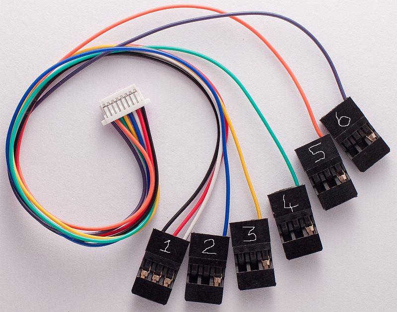
Cables, colours & pin-outs
CopterControl uses the JST-SH series headers. A CopterControl board comes standard with one 8-pin connection cable as shown below to connect your receiver. Additionally, one 4-pin JST-SH cable is supplied to connect to the MainPort or FlexiPort. You can easily cut the 4-pins cable and connect your telemetry or Spektrum satellite.
Power
Warning
MAKE SURE YOU ARE CONNECTING POSITIVE AND NEGATIVE CORRECTLY.
- CopterControl can be powered in several ways. Via the USB port, through the power pins on the servo headers or through the ReceiverPort connector (see the ports section for the port location). When powered by USB, peripherals connected (receiver, serial ports, servos, ESCs) will not be powered to protect your computer from too much current draw through the USB.
- The minimum allowed input voltage for CopterControl is 4.8V, the maximum allowed input voltage is +15V.
- Power consumption = ±70mA.
- You can connect the USB and the receiver (with the power) at the same time.
Caution
The PWR Out pins provide unregulated voltage to the ports. If the CC is powered from a +15V (max. allowed) source then +15V will be on the PWR Out pins and can damage connected receivers, GPS, telemetry modems or other add-on boards
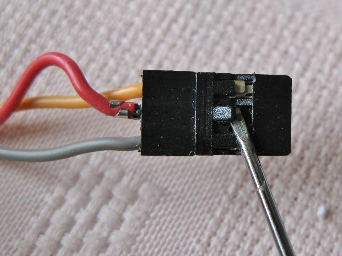
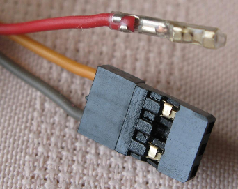
If you power the flight controller through the servo connectors (utilising the BEC function of the speed controller), the positive power lead from only one ESC is truly necessary. In most cases, all the wires can be left intact and plugged into the board without any problem. If you experience problems with setup or know for a fact that your particular ESC model requires it, you may remove the positive and negative pins from all but one of the ESC servo connectors. In some ESCs (very few, actually), connecting multiple voltage regulators (built in to the ESC’s) in parallel could cause problems. Also, in rare cases, connecting multiple ground wires could cause ground loops so remove the extra ground pins only if experiencing weird problems.
These photos show how to remove and insulate the positive wire from the ESC. Remove the positive & negative wire leaving only the signal cable connected for all but one of your ESC’s. A small flat blade screwdriver (or X-Acto knife could be used) and 2mm heat shrink tube was used in this example. This modification can easily be reversed by removing the heat shrink and inserting the positive wire back in to the ESC plug. Also, remove the ground wire when removing the hot and insulate separately from the hot wire.

Sensors and Components
- 3-axis Gyroscope array: IDG-500 and ISZ-500 [1]
- 3-axis Accelerometer: ADXL345 [1]
- Supports several common RC inputs: 6 PWM channels, combined PPM, Spektrum/JR DSM2, DSMJ, DSMX satellites, and Futaba S.Bus receivers
- Simultaneous support for multiple receivers
- ReceiverPort functions (configurable): 6 PWM input channels or combined PPM stream, 4 PWM output channels
- MainPort functions (configurable): serial telemetry (default), GPS, S.Bus, Spektrum/JR satellites
- FlexiPort (configurable): serial telemetry, GPS, Spektrum/JR satellites, or I2C peripherals (under development)
- 10 PWM outputs to servos or ESC’s, or for camera stabilization
- Camera stabilization: supports up to 3-axis camera mounts with stabilization and manual control from any of configured receivers
- On-board USB connectivity for easy configuration
- USB and serial telemetry and configuration (including wireless with optional radio modules)
- Supported by powerful OpenPilot GCS
- 4 Mbit on-board memory
- 3C Quaternion based complementary filter running at 500Hz
| [1] | On CC3D the IDG-500, ISZ-500 and ADXL345 is replaced by the MPU6000. |
DIY Boards
Schematics, PCB Layout, Gerbers, BOM for CopterControl: CopterControl.zip
Schematics, PCB Layout, Gerbers, BOM for CopterControl 3D: CC3D.zip
Schematics, PCB Layout, Gerbers, BOM for Atom: Atom.zip