LibrePilot System Architecture
- Eric Price
LibrePilot is an Open Source Avionics Solution for Unmanned Aerial Vehicles (UAV), Model Aircraft and other robots. It implements sensor fusion as well as fully configurable Steering, Control, Guidance and autonomous Navigation and runs on a flight controller circuit board. It interfaces with remote control receivers, GPS, IMU, Barometer and other sensors and controls a number of actuators such as brushless engines, navigation lights, buzzers, servos, etc...
1 Hardware Architecture
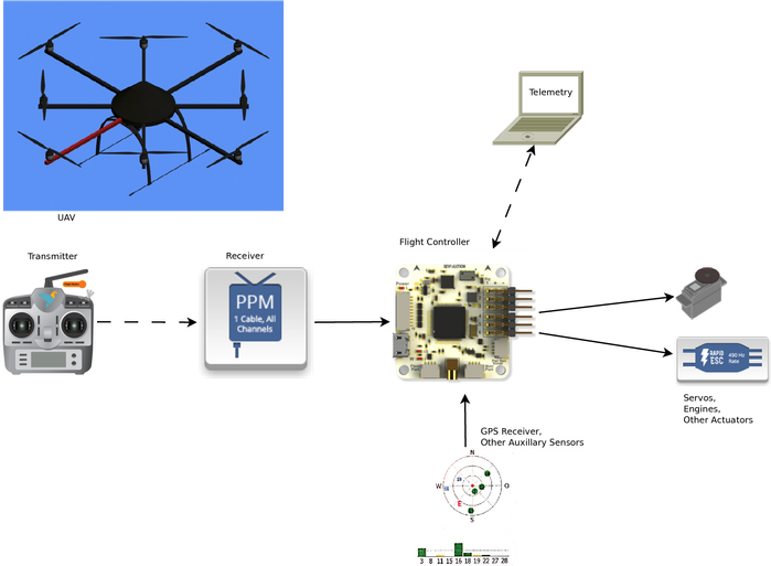
Figure 1 Hardware Architecture
A typical UAV or Model Aircraft will be controlled by a human operator with a remote control transmitter. It’s signals will be received by some sort of receiver, which in some cases would directly control the actuators. In case of multicopers and other vehicles with augmented control, a flight controller sits in between to interpret the control commands, then runs control algorithms on the vehicle. For this it is fusing information from integrated sensors typically forming an Inertial Measurement Unit (IMU) as well as possible auxiliary sensors such as a GPS receiver. The controller then steers the actuators such as engine controllers and servos.
2 Software Architecture
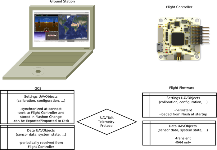
Figure 2 Software Architecture
2.1 Ground Control Software
The Ground Control Software (GCS) is typically running on a laptop. It is connected to the Flight Controller using USB, serial cables or some form of radio telemetry. The GCS is used to configure the Flight Controller and to monitor and log flight telemetry data. It can also act as a bridge for hardware in the loop simulation. It is implemented in C++ using the platform independent Qt5 framework.
2.2 Flight firmware
The Flight Firmware is running on the embedded Flight Controller and can operate both while connected to GCS or independently. It is implemented in Embedded C and C++ using the FreeRTOS embedded real time operating system and typically runs on ARM architecture micro controllers. Using a FreeRTOS emulator (“simposix”) the Flight Firmware can also be run on a (Linux)-PC for simulation and test purposes.
The LibrePilot Flight Firmware utilizes a hardware abstraction layer named “PiOS” on top of the FreeRTOS base, as well as a custom scheduler for delayed callback functions with realtime scheduling guarantees. PiOS contains drivers for various communication devices, sensors, actuators, persistent memory, etc... It allows accessing these using hardware independent abstract interfaces.
2.3 UAVObjects
All data is kept in well defined data containers called UAVObjects, which are defined at compile time using XML-description. Both persistent settings and transient run time data is kept in UAVObjects. Any defined UAVObject can be exchanged and modified by both GCS and Flight Firmware based on defined policies. Typically this is usually done using the UAVTalk Protocol.
2.3.1 UAVTalk protocol
The UAVTalk protocol is typically used to exchange UAVObjects between components that share the same set of defined objects. Typically the Flight Firmware and the GCS. UAVTalk implements messages to
- To send a UAVObject to the other side (with or without request for acknowledgement).
- To request the other side to send a specific UAVObject.
- To acknowledge a received object.
2.3.2 Settings UAVObjects
Settings UAVObjects are typically modified only on the GCS, then sent once per modification to the Flight Firmware. They are loaded at boot Time from Non Volatile Memory on the flight controller. The GCS can instruct the Flight Firmware to store such a UAVObject to Non volatile Memory. All settings are retrieved from the Flight Controller by the GCS when a new connection is established to synchronize the configuration. In the GCS, Settings can also be exported to or imported from disk.
2.3.3 Data UAVObjects
Data UAVObjects store runtime values such as sensor data, control commands or status information. They are typically only sent from the Flight Firmware to the GCS, usually at periodic intervals. A notable exception are control objects. These are data objects which are used to influence the runtime behavior, such as objects used for the Connection Handshake between GCS and Flight Firmware or for sending specific control commands for example to instruct the Flight Firmware to save a specific Settings Object to Flash memory or to Erase it. Data Objects can be Single- or Multi-Instance objects, examples for the latter are Waypoints in a navigation Route. These are also Control Objects.
2.4 GCS Plugins
Software components of the GCS are implemented as Plugins. Each plugin defines optional user interface widgets, which can be displayed on a tab within the GCS. For each plugin one or multiple widgets can be configured, each with its own settings.
Examples for plugins are:
- Primary Flight Display - It displays an artificial horizon as well as a large amount of data
- OPMap - It displays a world map and the location of the vehicle as well as waypoints and other locations on it.
- System health - It displays a colorful display of the state of various alarms.
- Scope - Scopes can graphically display the content of any UAVObject such as sensor data at runtime, as well as log their contents to a CSV file.
- UAVObjectBrowser - The UAVObjctBrowser allows to display and modify the contents of every defined UAVObject, instruct the Flight Firmware to load, save or dele a UAVObject from Flash memory, and modify the data transfer rules and intervals for all UAVObjects.
- ...
Plugins usually operate on one or more UAVObjects which are either read and displayed or modified or both. Each modification of any UAVObject - for example when it is received from the flight firmware or modified by another plugin - triggers an event which any plugin can respond to.
2.5 Flight Firmware Modules
Software components within the Flight Firmware are implemented as Modules. Modules can exist both in form of threads or callback functions.
Their execution can be triggered either by hardware events (such as availability of new sensor data) or by the update of specific UAVObjects.
Modules communicate exclusively using UAVObjects, both between each other and with the GCS.
Examples for Firmware modules are:
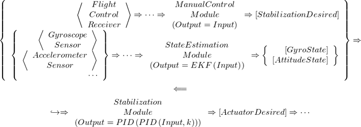
- Sensors Module - This module receives data from the controllers on board sensors such as Gyroscope, Accelerometer and stores the measurement data in their respective UAVObjects: GyroSensor, AccelSensor, ...
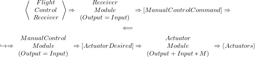
- Receiver Module - This module receives data from the connected flight control receiver, verifies its integrity and possible failsafe situations and stores the result in respective UAVObjects: ManualControlCommand
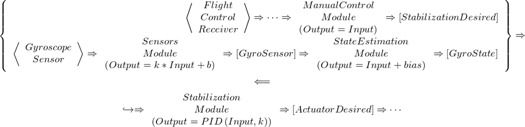
- ManualControl Module - This module interprets the data in ManualControlCommand and sets other UAVObjects based on the flight mode and control input. This includes the FlightStatus UAVObject itself which stores the current flight mode, engine arming state, etc..
- StateEstimation Module - This module fuses data from various sensors using filters and calculates derived state information. The most important derived state UAVObject is AttitudeState which holds the vehicles orientation in 3d space. The Attitude can not be measured directly but only using one of several implemented filters.
- Stabilization Module - This module reads the control set point for flight control from the StabilizationDesired UAVObject - set for example by the PathFollower or by ManualControl - and calculates the required control output stored in the ActuatorDesired UAVObject
- Actuators Module - This module reads the desired control output from ActuatorDesired, applies the Mixer Matrix and drives servos and engines accordingly.
- Telemetry Module - This module is responsible for exchanging and synchronizing UAVobjects with the GCS utilizing a com device.
- PathPlanner - This module implements the navigation computer as a state machine. Waypoints and pathactions are interpreted to define behaviors and transition conditions. The current behavior is written to the PathDesired UAVObject, and then interpreted by the
- PathFollower - This module is the “autopilot” of the flight controller. It interprets the behavior in PathDesired which - depending on flight mode - can be set by either the ManualControl module or by the PathPlanner navigation computer. It runs vehicle specific control loops and eventually calculates the set point for the flight stabilization stored in StabilizationDesired.
- ...
3 Control Architecture
The control architecture is dependent on flight mode and settings. This document describes a few noteworthy examples and how they are implemented.
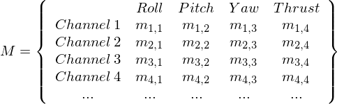
All Modes share a common vehicle agnostic control channel abstraction, where each control channel can assume values between -1 and +1. The following control channels are defined, as seen in the ActuatorDesired UAVObject:
- Roll - Defines the control command for rotation around the X axis, mapped to actuators for example using aileron servos or differential thrust between left and right rotors. 0 means neutral, +1 means maximum clockwise rotation, -1 means maximum counter clockwise rotation.
- Pitch - Defines the control command for rotation around the Y axis, mapped to actuators for example using elevator servos or differential thrust between back and front rotors. 0 means neural, +1 means maximum nose up rotation, -1 means maximum nose down rotation.
- Yaw - Defines the control command for rotation around the Z axis, mapped to actuators for example using rudder servo or differential thrust between clockwise and counter clockwise rotating rotors, or speed of a tail-propeller. 0 means neutral, +1 means maximum nose right rotation, -1 means maximum nose left rotation.
- Thrust - Defines the control command for the actuator that controls energy. For a fixed wing or multirotor craft this might be collective engine throttle, for a glider it might be applied in reverse to breaking flaps. For a helicopter it might be collective pitch. 0 means neutral, +1 means maximum positive thrust (full throttle) -1 means maximum negative thrust (maximum break or reverse thrust)
These virtual control channels are mapped to physical actuators using a Mixer Matrix which is stored in the MixerSettings UAVObject along with information about the channel type.
3.1 Manual Control
In Manual Control Mode, the ManualControlCommand coming from the control receiver is directly fed to ActuatorDesired. As such the flight controls directly steer the actuators in open loop control. The pilot actuating the control transmitter closes the loop using hand eye coordination or relies on aerodynamic flight stability.
3.2 Stabilized Control
In Stabilized Control Mode, the ManualControlCommand from the receiver is fed into StabilizationDesired. In Rate mode, a single PID control loop is used for control, while in Attitude mode, two cascaded PID loops are used where the outer loop controls the angular velocity setpoint based on attitude error, and the inner loop controls the actuator based on angular velocity errors.
3.2.1 Rate Control
3.2.2 Attitude Control
3.3 Autopilot Control
In control Modes that involve the Autopilot, the craft is flown by the Flight Controller based on the trajectory instructions in the PathDesired UAVObject. This is initialized to the current position in “Position Hold”, set dynamically based on the ManualControlCommand in various assisted flight modes, or might even be set by the Navigation Computer implemented in PathPlanner module, which traverses a conditional graph of waypoint coordinates.
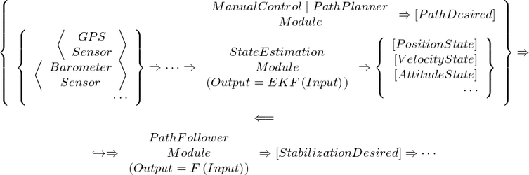
The control algorithm F varies based on vehicle type and also the PathMode requested in the PathDesired UAVObject. At the time of writing this document the supported control modes are:
- GoToEndpoint - The Autopilot will try to hold position at a fixed end-coordinate. If elsewhere, the craft will steer towards the coordinate but not necessarily in a straight line as drift will not be compensated.
- FollowVector - The Autopilot will try to fly in a straight line from the start to the end-coordinate and possibly beyond. The craft will fly in a straight line and correct any sideways deviation from the desired path.
- CircleRight,CircleLeft - The Autopilot will try to circle around the end-coordinate in a fixed distance given by the start coordinate. The craft will correct distance deviations.
- FixedAttitude - The Autopilot will set a fixed attitude as a setpoint for Stabilization - regardless of orientation or velocity.
- SetAccessory - The Autopilot will set auxiliary output channels, for example to blink lights, open payload bays, lower or rise gear, ...
- DisarmAlarm - The Autopilot will initiate an autonomous disarming sequence which will cut power/fuel to all engines. Useful after landing...
- Land - The Autopilot will engage a hardcoded, fully automated landing sequence.
- Brake - This is used internally by assisted flight modes to slow down.
- Velocity - The Autopilot will attempt to maintain a velocity in 3d space.
- AutoTakeoff - The Autopilot will engage a hardcoded, fully automated takeoff sequence.
It is needless to say that correct function of the autopilot is dependent on a myriad of factors, including but not limited to
- correct calibration of all sensors
- suitable tuning of Stabilization PID coefficients
- suitable tuning of the Autopilots own control parameters