OpenPilot Revolution
- Andraž
- Lalanne Laurent
- Dave G
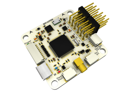
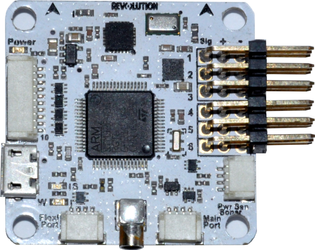
The Revolution is a full 10DoF flight controller board capable of stabilizing various aircrafts ranging from small racing miniquads to large FPV fixed wing models and aerial photography platforms.
Along side standard stabilization modes it also supports various GPS assisted modes and GPS navigation flight.
Hardware Description
CPU
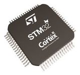
Main processor is a STM32F405RGT6 ARM Cortex-M4 microcontroller.
Sensor Suite
Revolution's 10DoF are provided by:
- Invensense MPU6000 digital MEMS Gyro/Accelerometer
- Measurement Specialties MS5611 Barometer
- Honeywell HMC5883L Magnetometer
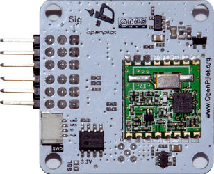
Integrated 433MHz radio
Integrated HopeRF RFM22B 100mW 433MHz radio can be used with an OPLink modem for wireless telemetry, configuration and control.
Dimensions
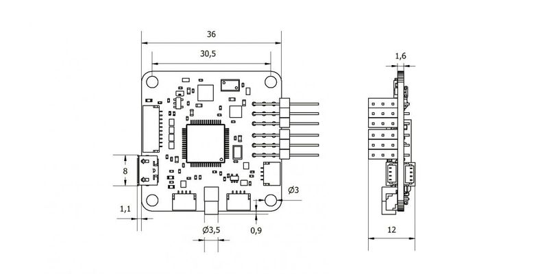
36x36mm with 30,5x30,5mm hole spacing
Connectivity
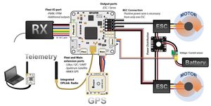
Powering the board
Board can be powered with 4,8-10V DC power supply, usually from one of ESCs integrated BECs or an external 5V BEC. The voltage used to power the board will also power any peripheral devices like GPS, Bluetooth modem,... connected to it.
All input/output (Rx, Tx, PWM, etc.) signal levels are 3,3V (5V tolerant)
All Vcc pins are can be used to power the controller and devices connected to it.
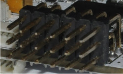
PWM Outputs 1-6
These are PWM outputs used to connect servo motors and ESCs. Outputs 5 and 6 can also be configured as analog inputs
Supported protocols:
- Standard PWM with configurable rate from 50Hz to 490Hz
- PWMSync (PWM synchronized to the gyro sampling rate)
- OneShot125
Pinout:
PWM Out 6 | PWM Out 5 | PWM Out 4 | PWM Out 3 | PWM Out 2 | PWM Out 1 |
| Vcc | Vcc | Vcc | Vcc | Vcc | Vcc |
| GND | GND | GND | GND | GND | GND |
FlexIO Port
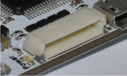
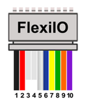
It's primary use is as a receiver port compatible with PWM and PPM receivers, but can also be used to provide up to 6 additional PWM outputs, serial telemetry port, and two GPIO pins.
The connector used is a 10pin JST-SH
Pinout:
| Pin | Wire Color | PPM In | PWM In | Telemetry | PWM Out |
|---|---|---|---|---|---|
| 1 | Black | GND | |||
| 2 | Red | Vcc (4,8-10V DC) | |||
| 3 | |||||
| 4 | |||||
| 5 | White | PPM In | PWM In 1 | PWM Out 12 | |
| 6 | Blue | PWM In 2 | PWM Out 7 | ||
| 7 | Yellow | PWM In 3 | Tx | PWM Out 8 | |
| 8 | Green | PWM In 4 | Rx | PWM Out 9 | |
| 9 | Orange | PWM In 5 | PWM Out 10 | ||
| 10 | Violet | PWM In 6 | PWM Out 11 | ||
Main Port
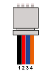
This is a UART serial port with a programmable inverter on the Rx pin. It can be used to connect various serial devices such as GPS receiver, OSD, Telemetry (Bluetooth, OPLink, etc.), S.Bus receiver, DSM satellite receiver...
The conector used is a 4pin JST-SH.
Pinout:
| Pin | Wire Color | Telemetry | GPS | OSD | DSM | S.Bus |
|---|---|---|---|---|---|---|
| 1 | Black | GND | ||||
| 2 | Red | Vcc (4,8-10V DC) | ||||
| 3 | Blue | Tx | ||||
| 4 | Orange | Rx | DSM In | S.Bus In | ||
The Tx and Rx lines between the controller and device must be connected: Rx to Tx and Tx to Rx. If you connect Rx to Rx and Tx to Tx, serial communication will not work.
Flexi Port
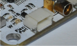
This port can support both UART and I2C serial devices, such as external I2C sensors (external magnetometer), GPS, OSD, Telemetry, DSM receiver, SRXL receiver,...
The connector used is a 4pin JST-SH.
Pinout:
| Pin | Wire Color | Telemetry | GPS | OSD | DSM | SRXL | I2C |
|---|---|---|---|---|---|---|---|
| 1 | Black | GND | |||||
| 2 | Red | Vcc (4,8-10V DC) | |||||
| 3 | Blue | Tx | SCL | ||||
| 4 | Orange | Rx | DSM In | SRXL In | SDA | ||
The Tx and Rx lines between the controller and device must be connected: Rx to Tx and Tx to Rx. If you connect Rx to Rx and Tx to Tx, serial communication will not work.
Pwr Sen/Sonar Port
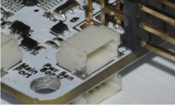
This port has two analog inputs that can be used to connect analog sensors such as voltage, current, analog airspeed sensor... It can also be used to connect a sonar, but that functionality currently isn't implemented.
The connector used is a 4pin JST-SH.
Pinout:
| Pin | Analog In | |
|---|---|---|
| 1 | GND | |
| 2 | Vcc | |
| 3 | ADC 0 | |
| 4 | ADC 1 |
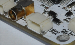
Antenna Connector
433MHz antenna for the integrated modem should be connected here.
Never use (set output power to more than zero) the integrated radio without an antenna attached.
Turning on the integrated radio with no antenna attached can cause permanent damage to the integrated radio module.
The connector used is MMCX
USB Port
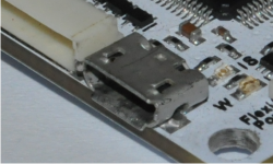
A standard Micro-B USB connector such as found on most modern cell phones used to connect to the PC.
The flight controller presents itself to the PC as a HID (Human Interface Device) and VCP (Virtual Com Port) device.
The HID part comes configured for telemetry and is used to configure, update and debug your flight controller.
The VCP can be used for telemetry and ComBridge functionality which binds Main or Flexi port to be used as a com port from your PC (useful for configuring your OSD without needing to rip it out of your airframe)
This connector will provide power to the processor and sensors but will not power any externally connected devices.
SWD Port
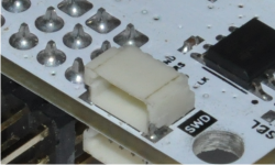
This port is used by developers for flashing and debugging the firmware. Most users will never have to use it.
Pinout:
| Pnn | Function |
|---|---|
| 1 | GND |
| 2 | NRST |
| 3 | SWDIO |
| 4 | SWDCLK |