Versions Compared

Key

  • This line was added.
  • This line was removed.
  • Formatting was changed.

Overview

Section
Column
width60%

Image Added

KeyDescription
1

Configuration options

2

RxLevel

3

Status

Column
width250px
Panel
titleIn this page
Table of Contents


...


Section
Section

Hardware

Column
width50%

Revolution board

Revolution board with integrated modem

100mW RFM22 Radio Modem

MMCX Antenna Connector.

Input Voltage: +5V recommended, same power is used for accessories like GPS or Rc receiver!

Frequency: 430-440Mhz

Column
width50%


Section
Column
width50%

Sparky2 board

Sparky2 board with integrated modem

100mW RFM22 Radio Modem + ceramic low pass filter

UFL Antenna Connector.

Input Voltage: +5V recommended, same power is used for accessories like GPS or Rc receiver!

Frequency: 430-440Mhz

Column
width50%


350px
Section
Column
width50%

OPlink Mini

100mW RFM22 Radio Modem

Input Voltage: +5V recommended, up to 2S battery - 8.4V if used as Rc Tx module.

Frequency: 430-440Mhz

3 IO Ports: Micro-B USB, MainPort and FlexiPort

MMCX Antenna connector.

Weight: 4g

Dimensions: 20mm x 29mm

Column
width50%


Column
width

Panel
titleIn this page
Table of Contents


...

Binding

Section
Column
width50%

Coordinator side (Ground)

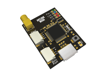
1. Connect to the OPlink mini Ground module that you are going to use as Coordinator.
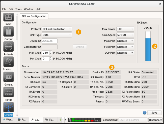
2. Go to the OPlink page in the GCS, available on the Configuration tab’s left bar. It is only visible if an OPlink, Revolution or Sparky2 is connected.
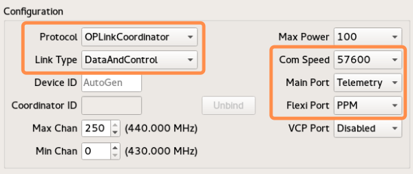
3. Set the following recommended settings:

a. 'Max Power' 100mW (or maximum for your country)
b. 'Com Speed' 57600 (or 38400 if you take care about refresh rates)
c. 'Max chan' 250 (75 - USA requires Amateur Radio License)
d. 'Min chan' 0 (53 - USA requires Amateur Radio License)
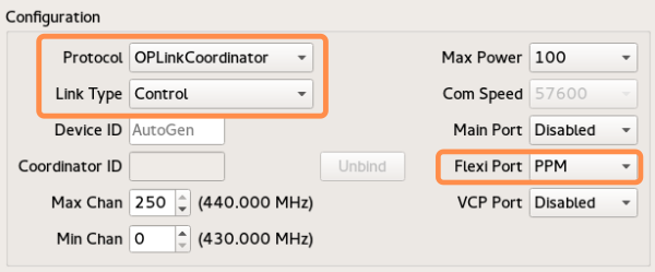
e. Select the Protocol as OplinkCoordinator.
f.  Select the Link type as Data
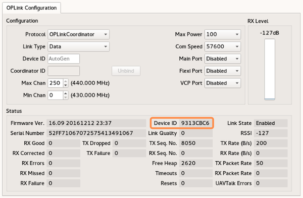
g. Click Save, wait a few seconds for the telemetry gadget (the meter at the bottom of the GCS) to calm down.

4. Disconnect / Reconnect your OPlink mini modem, this enables modem and show Device ID. At this point a custom device ID can be defined by user, not auto-generated.

5. Write down the Device ID. You are going to use it later.

6. Disconnect from the coordinating module.

The OPlink Save button will display a green 'tick' when settings are saved, but it can disappear soon after settings are saved. This is normal behavior.


Info
titleUsing custom frequencies

If your country allows only a fraction of the available frequency band to be used, you can adjust the operational OPlink channel range to reflect that.
The GCS indicates minimum and maximum used frequency when you change min and max channels. While operate, the link will do channel hopping within this range.

Both OPlinks must have the same min and max channel pair to bind successfully.

Warning
titleAbout antennas

Since you set something different than 0 for Max Power setting, the board will transmit.
If USB is connected, the RF module is powered and can transmit.

Be sure you connected the antenna to MMCX connector or RF module can burn. This is not reversible!

This also means a "0" value disables the Oplink and you can safely use the Revolution board without his antenna.

Column
width50%


...

Dual OPlink for Remote control

Section

Image RemovedImage Added


Section
Column
width50%

Ground OPlink setup

Same as above:

  • Set the Protocol as OPLinkCoordinator
  • Set the Link Type as Control
  • FlexiPort is set to PPM


Column
width50%


...

Telemetry + Remote Control + Bluetooth

Section

Image RemovedImage Added

This configuration allow a "wireless" setup with remote control and telemetry back to computer.

This need a Bluetooth module already setup for 57600bauds. See how to configure the Bluetooth module in this page.

Section
Column
width50%

Ground OPlink setup

Ground OPlink is connected to the RC radio using the connector from Tx module or using the PPM signal from trainer port.

Voltage can be up to 2S battery (8.4V)

Image RemovedImage Added


  • FlexiPort is set to PPM used for PPM input from Remote controller.
  • MainPort is set as Telemetry for output to bluetooth module.
  • Baudrate at 57600 bauds
  • Ground OPLM protocol is set to OPLinkCoordinator
  • Link type is set to DataAndControl.
Column
width50%


...