Versions Compared

Key

  • This line was added.
  • This line was removed.
  • Formatting was changed.

...

Section
Column
width60%

This step is optional, but highly recommended. It reduces Accelerometer/Gyro or Barometer drift.

During this step the controller monitor temperature changes while warm up and record the sensor values. At end the controller compute curves that compensate drift for every sensor within the temperature range used for calibration. No need a -40°C > +80°C range, but temperature calibration should be done at working temperature while flying in normal conditions.

  1. Connect a USB cable to the controller and then put the board in a plastic bag, seal the bag and remove air from inside. Leave USB cable outside the bag so that it can be connected to the computer later. This will protect the board from condensation or moisture.
  2. Place the bagged controller/USB cable assembly into the freezer for approximately 20 minutes.
  3. Remove the bag from the freezer, connect the USB cable to the computer, wait the connection and start the thermal calibration with the Start button.

    Info
    titleRecommendations

    Avoid lamp use for warming, barometer sensor is very sensible to light !

    While the controller warm up, just keep the board still, close to a heat source like a radiator.

  4. Wait the calibration end, when the temperature gradient is too small, the calibration end automatically.
  5. Save calibration results

Thermal calibration can be saved for this board see UAV Settings Import-Export page.


Column
width40%

Protect controller from moisture and condensationImage RemovedProtect controller from moisture and condensationImage Added

 Image RemovedImage Added


...

Accelerometer calibration

Section
Column
width60%

Because Accelerometer sensor measure gravity, Home Location need to be set first. Please look the Setting Home location page.

This calibration should give a best accuracy so controller know his real orientation in space. Calibration adjust Accel bias but also Accel scales.

This calibration should be done while the controller is unmounted on frame, a controller case is preferred and allow accurate/stable positions.

The controller can be adjoined against a box for best position.

To initiate the Accelerometer calibration, press the Start button. Follow the onscreen instructions, orienting the controller as shown and pressing Save Position .

On every step when the position is saved, the controller need to be perfectly still !

After calibration is successful, save calibration results with Save button.

Image RemovedImage Added

Accelerometers calibration result can be displayed on UAVOBrowser: accel_bias and accel_scale.

Image RemovedImage Added

Column
width40%

 Image RemovedImage Added

Image RemovedImage Added

...

Magnetometer calibration

Section
Column
width60%

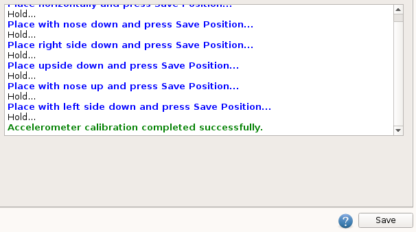
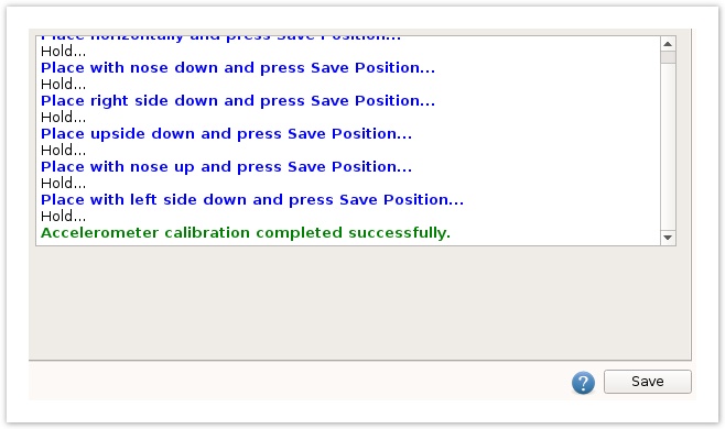
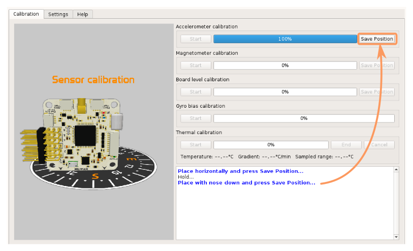
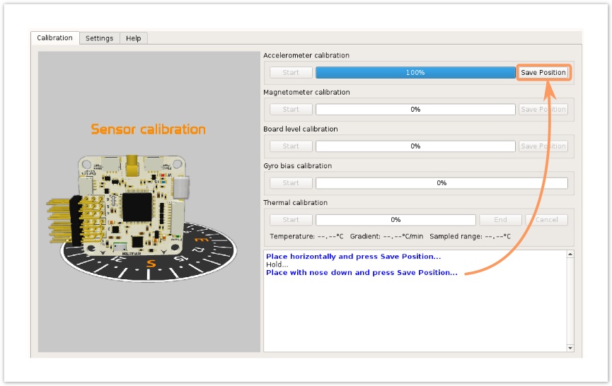
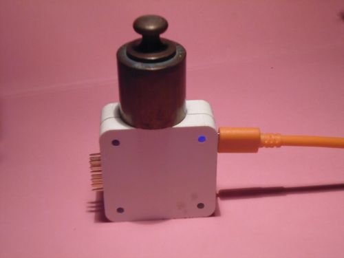
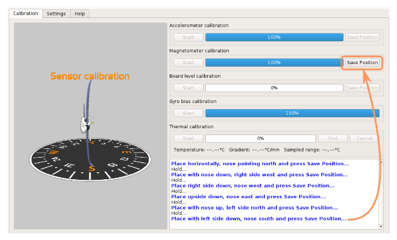
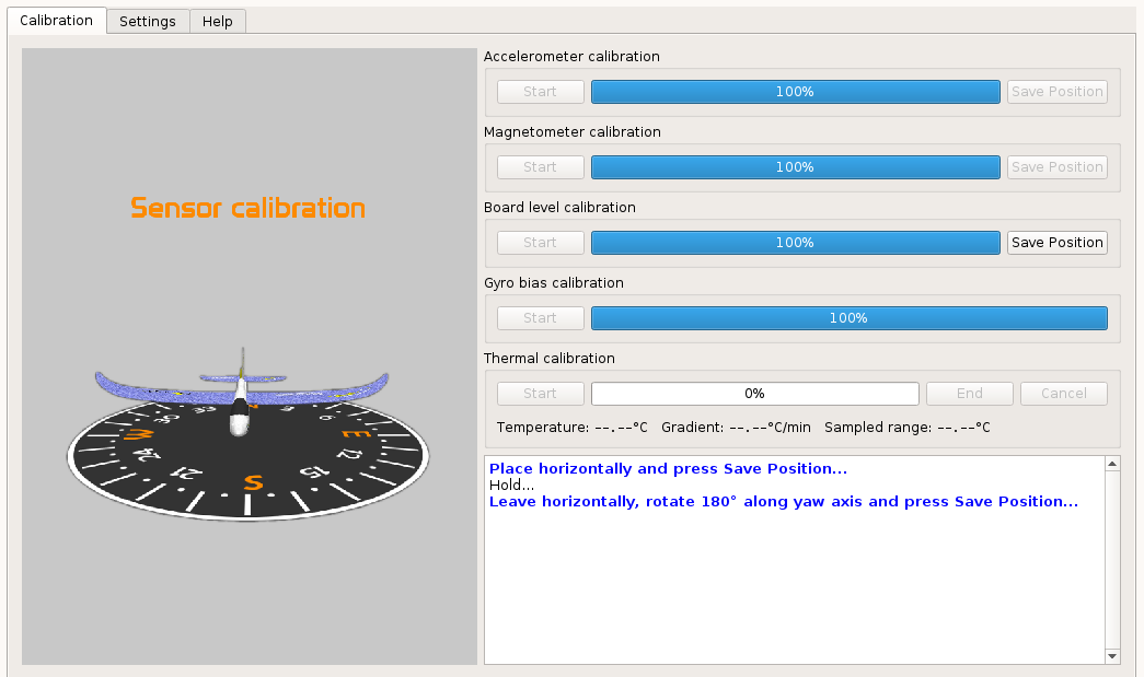
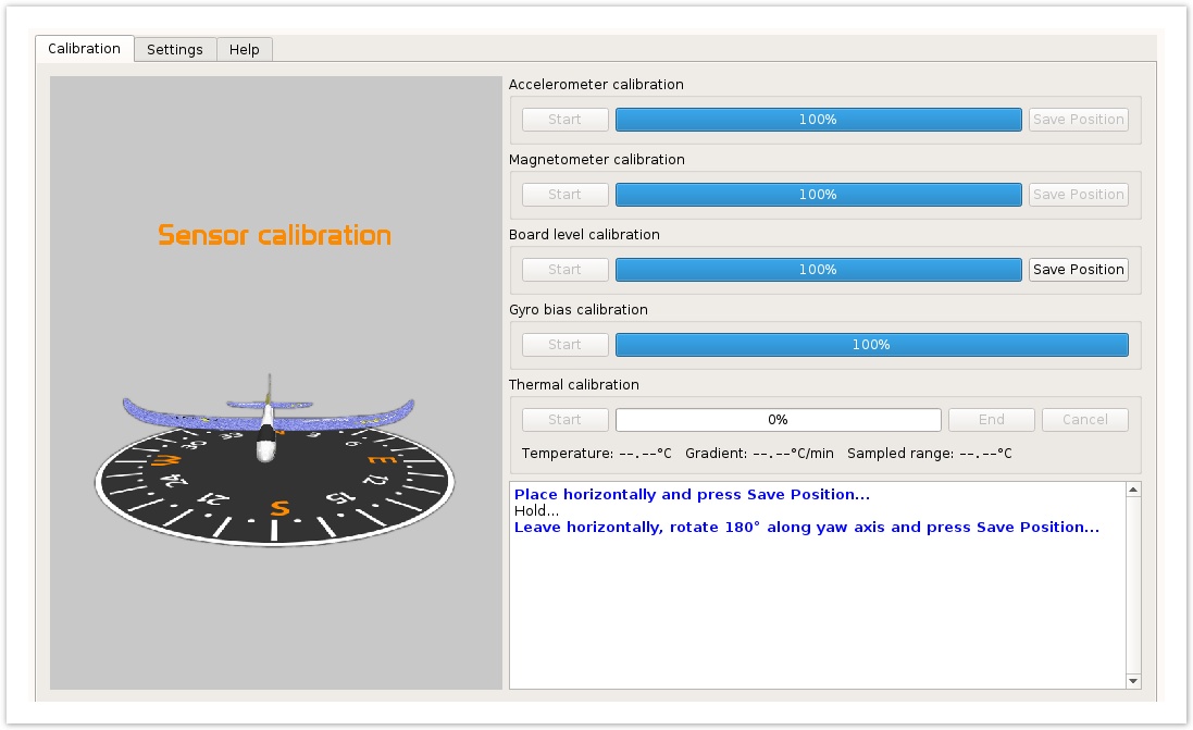
Prior to magnetometer calibration, the Home Location need to be set, please look the Setting Home location page.

Using the know location and the World Mag Model data , the controller computes the Mag vector expected.

Be sure the controller is mounted on frame in his final configuration, power wires twisted and away from unwanted electromagnetic fields.

To initiate the magnetometer calibration, press the Start button. Follow the onscreen instructions, orienting the controller as shown and pressing Save Position at each step. There is no need to align the vehicle exactly south, north, east or west during the individual steps. The directions indicated serve only to tell you in which direction the airframe should be positioned relative to some point. One can simply assume that North is in front of you, East is to the right, West is to the left and South is pointing at you.

Another method consist on validate the five first steps, move/rotate vehicle on all axis and finally save the last step.

Calibration should be performed outdoors, Oplink or Bluetooth connection give best results.


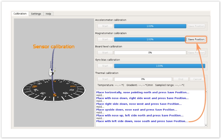
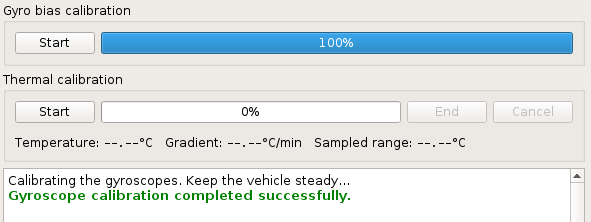
After mag calibration is successful, save calibration results with Save button.

Column
width40%

Image RemovedImage Added

...

Board level calibration

Section
Column
width60%

To initiate the Board Level Calibration, place the vehicle on a flat, level surface and press the Start button.

Follow the onscreen instructions, doing the two measurements.

Save Position each time when it is perfectly still.

After level calibration is successful, save calibration results with Save button.


Info
titleVirtual Attitude

If you are using a custom virtual board orientation (Roll or Pitch) be sure you set and save values prior to this level calibration.

Column
width40%

Image RemovedImage Added

...

Gyro bias calibration

Section
Column
width50%


This step will allow you to calibrate the gyro measured value when the board is steady.

To perform the calibration leave the board/airframe completely stationary and press Start.


After gyroscope calibration is successful, save calibration results with Save button.

Column
width50%

 Image RemovedImage Added

...


...