| Section |
|---|
| Column |
|---|
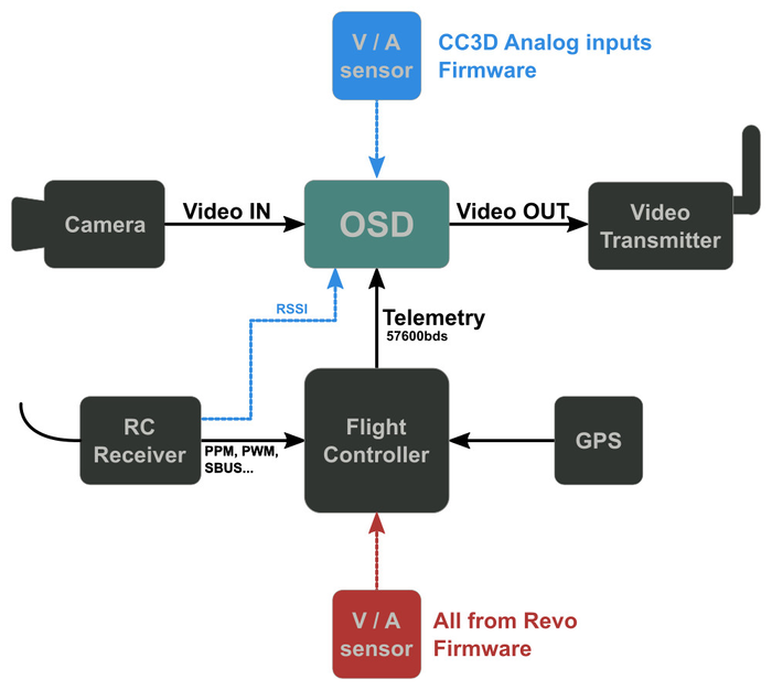
| IntroductionSome years ago Joerg-D. Rothfuchs (JR63) added UAVTALK protocol to minimOSD firmware to allow communication between MinimOSD and OpenPilot boards.The MinOPOSD is born. Useful info still available in the following pages: The OSD (On Screen Display) enables useful information to be superimposed on a video signal to an FPV pilot.
Connection diagram
|
|
...
| Description | Board supported | Analog inputs | Firmware file |
|---|
All analog inputs connected to OSD board. RSSI, Vbat, Current. MinimOSD or Micro KV Team Needed for CC3D who can't support current sensor. |
All boards | yes Rssi, Vbat, Current |
|
Nothing connected to OSD hardware, all information comes from flight controller. RSSI information comes from link quality UAVO. Voltage/current sensor can be connected to Revolution board, See Configure a Current-Voltage sensor |
Revo only |
No | | Revo1708 |
Same as above Voltage/current sensor connected to Revo + analog RSSI connected to OSD. |
Revo only |
RSSI | Revo1708Revo1708 |
The config tool used for OSD configuration : ConfigTool_minOPOSD.zip
...
| Section |
|---|
| Column |
|---|
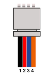
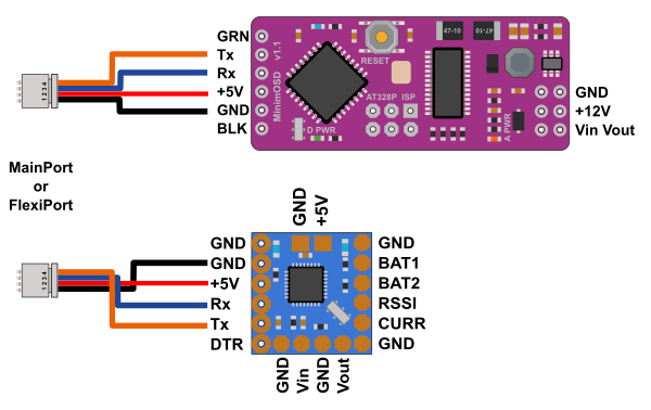
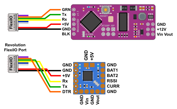
| All boardsCommunication between flight controller and OSD is done using a serial telemetry at 57600bauds. JST connector Main / Flexi port | Connector pin (board) | Description | MinimOSD |
|---|
| 1 | GND | GND | | 2 | VCC | +5V | | 3 | Tx | Rx | | 4 | Rx | Tx |
Please note Tx/Rx lines are crossed
Configure one port with telemetry at 57600bauds, can be MainPort or FlexiPort.
|
| Column |
|---|
| 

|
|
...
Revolution only
| Section |
|---|
| Column |
|---|
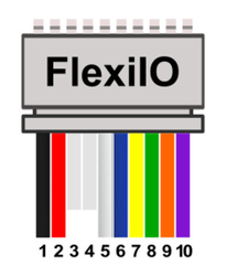
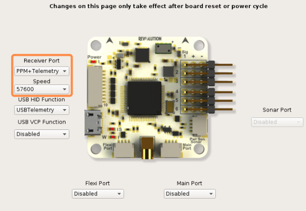
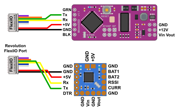
| | Revolution board can provide extra telemetry on FlexiIO port (receiver port), for normal operation no need the DTR pin wired.
JST connector Revolution FlexiIO | Connector pin (board) | Description | MinimOSD |
|---|
| 1 | GND | GND | | 2 | VCC | +5V | | 7 | Tx | Rx | | 8 | Rx | Tx | | 9 (for programming) | DTR | GRN or DTR |
Two options are available for telemetry output on FlexiIO (receiver) port: TELEMETRY or PPM+TELEMETRY |
| Column |
|---|
| |
 |
|
...
Programming setup
| Section |
|---|
| Column |
|---|
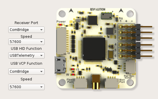
| Using Revolution boardWith the Revolution board you can use the FlexiIO port for telemetry and optional DTR pin is wired with MinimOSD. Please note the programming cannot be done without DTR pin wired. First you need to setup Revolution board as follows : 1 - Connect Revolution board to the computer 2 - Go to the Configuration Tab and Hardware tab 3 - For USB VCP function, select ComBridge
4 - In Receiver Port, select ComBridge 5 - Save and reboot board
Now you can connect the receiver port with the minimOSD board, be sure the revolution board is powered with 5V |
| Column |
|---|
| 
|
|
...
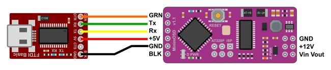
Using a FTDI device
| Section |
|---|
| Column |
|---|
| | Connect FTDI device with MinimOSD as follow |
| Column |
|---|
| 
|
|
...
Firmware upload
There is two chips on MinimOSD board, one is a Atmel 368P and the other is a MAX7456 (video chip)
...
| Section |
|---|
| Column |
|---|
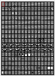
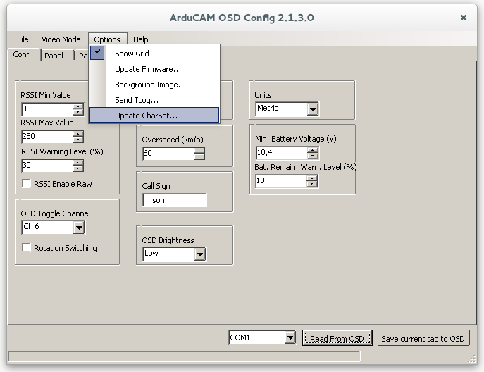
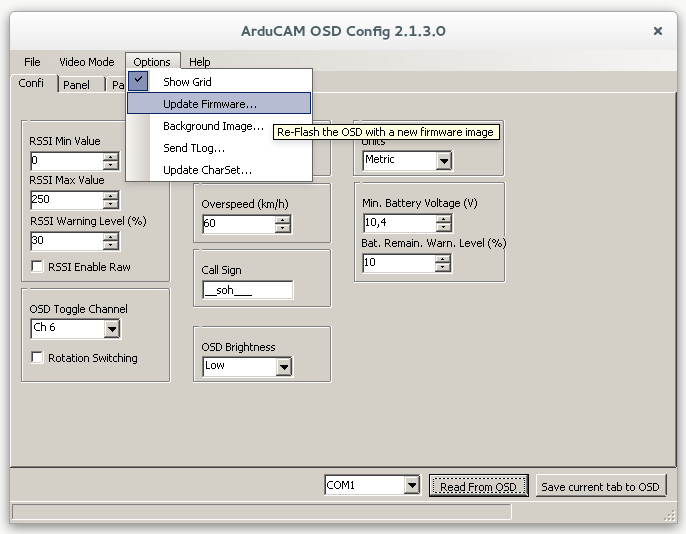
| First update character set stored inside MAX7456 chip, be sure the video side is also powered. Some MinimOSD board need +12v on video side or 5v mods. 1 - Select the right port, in this example COM1 2 - Go to Options menu and Update Charset... 3 - Select the character set file (Charset_1_3_0.mcm) where you saved it on your hard drive. 4 - Wait the process is complete, this can take some time.
| Expand |
|---|
| title | About charset file... |
|---|
| | Section |
|---|
| Column |
|---|
| |
Character set contains all characters used by the MAX7456 chip, it should be updated or OSD display can be wrong like letters or others exotic characters shown. |
| Column |
|---|
| 
|
|
|
|
| Column |
|---|
| 
|
|
Update firmware
...
| Section |
|---|
| Column |
|---|
| 1 - Select the right port, in this example COM1 2 - Go to Options menu and Update Firmware... 3 - Select the firmware file (.hex) where you saved it on your hard drive. See Downloads. 4 - Wait the process is complete. |
| Column |
|---|
| 
|
|
...
| Section |
|---|
| Column |
|---|
| Video standard can be PAL or NTSC, selected by software and MinOPOsd talk with video chip to apply changes.
Go to Video Mode menu and select PAL or NTSC according to the camera used. 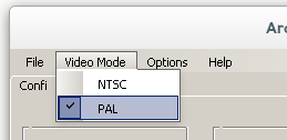
Don't forget the Save current tab to button to apply changes.
|
| Column |
|---|
| | | | PAL:16lines x 30columns | NTSC: 13lines x 30columns |
|
|
...
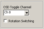
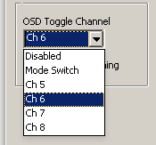
- Allow screen switching between Panel1, Panel2 and a empty panel.
- Enter Setup screen just after boot
...
| Section |
|---|
| Column |
|---|
| | Info |
|---|
| Note the default panel is Panel1 while any alarm is active: (DISARMED,LINK QUALITY, LOW BATTERY...) and you cannot switch to other screen/panel. |
Disabled: No screen changes, stay in Panel 1 Mode Switch: Uses the FlightMode switch, if you switch from a FlightMode to another than back within 2 sec, than will jump to the next screen. Ch5 to Ch8: Assign a channel for screen switching, should be 3 positions switch. Those "Channels" do not refers to real channel found in RC receiver but mapped like this: - Ch5: The flight mode switch (this means you can see for example Panel1 in Attitude mode, Panel2 in Rate mode and empty screen in Rattitude mode),
- Ch6: The Accessory0 as defined in Input tab,
- Ch7: The Accessory1 as defined in Input tab,
- Ch8: The Accessory2 as defined in Input tab.
Rotation Switching option: When checked, a momentary switch can be used (Ch5 to Ch8 defined). Every time you move switch OSD jump to next screen. Panel1, Panel2, Empty, Panel1... |
|
...
| Section |
|---|
| Column |
|---|
|  |
|
...
| Section |
|---|
| Column |
|---|
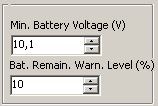
| Defines the level that triggers the "Low battery" alarm.
|
| Column |
|---|
| 
|
|
...
Panel setup
...
| Section |
|---|
| Column |
|---|
| Some parameters can be modified using the Rc transmitter, toggle switch and Pitch/roll stick. Just after boot, move the Toggle switch and you enter the Setup screen. Pitch stick change parameter while Roll stick allow parameter/value adjustment: - UAVTALK : Active or passive,
- TEMPDISP: Choose Baro temperature or TxPID values display for the "Temperature" field,
- BATTERY WARNING: adjust battery level.
Only with firmware using analog inputs: - CALIBRATE: monitor volt/amp values and adjust factors/amp offset
- Measured volt: Volt div ratio
- Measured amps: Amps offset
- Measured amps: Amps per volt
|
| Column |
|---|
| | Widget Connector |
|---|
| width | 640 |
|---|
| url | https://www.youtube.com/watch?v=C589Eh7PXDw |
|---|
| height | 480 |
|---|
|
|
|
...
| Section |
|---|
| Column |
|---|
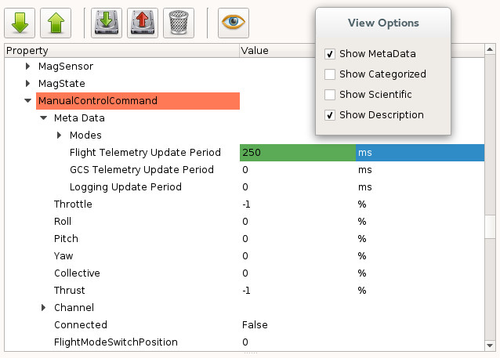
| Refresh rates should be fine for normal (flight) use. For setup screen changes and easy stick response you should modify ManualControlCommand refresh rate.
1 - Go to System tab 2 - In UAVOBrowser click View options button  and check Show Metadata and check Show Metadata
3 - Browse the the "Data" part and find ManualControlCommand UAVO
4 - Click the little arrow close to the Meta Data field
5 - Change Flight Telemetry Update Period to something lower, like 250ms 6 - Save changes
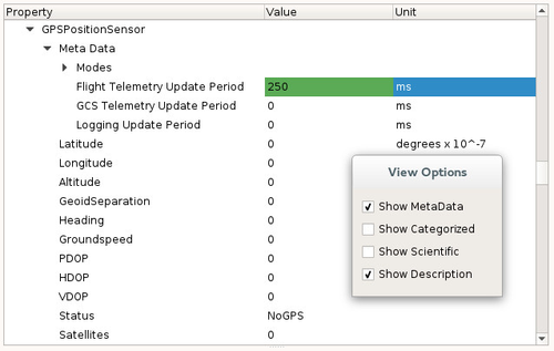
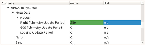
Others UAVObject rates can be modified and lowered as well, for smooth position and velocity changes: - GPSPositionSensor
- GPSVelocitySensor
|
|
...