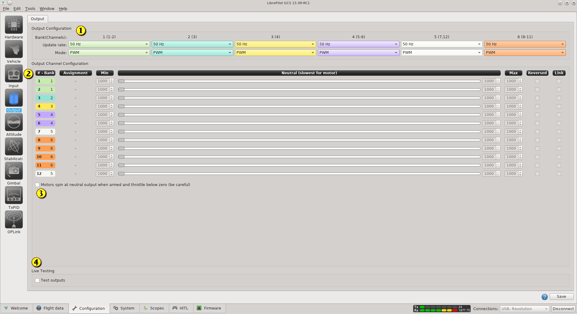
Overview
| Key | Description |
|---|---|
| 1 | Output Configuration: PWM mode has a configurable update rate, from 50Hz to 490Hz. The usual rate for multicopter speed controllers is 490Hz, but if the channel is used to drive a servo, 50Hz (analog servo) or 330Hz (Digital servo) should be used. The mode selection is PWM, PWMSync (Simonk Esc) and OneShot125 (BLHeli Esc). See the PWM, PWMSync, Oneshot Output page for more details. |
| 2 | The output signal to the channel can be set using the widgets in this section. The neutral speed is important - it is the slowest speed the motor will start and run consistently. In flight, the flight controller will not command the motor below this level during normal manoeuvres. |
| 3 | You can set the motors to spin at the neutral speed when armed, and even if the throttle is set below zero. |
| 4 | The live testing checkbox allows the channel outputs to be tested |
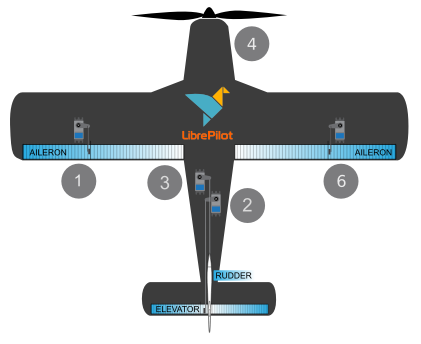
Banks and Outputs
Here is a typical configuration used with a Flying Wing and a CC3D board. Banks are not the same in all boards.
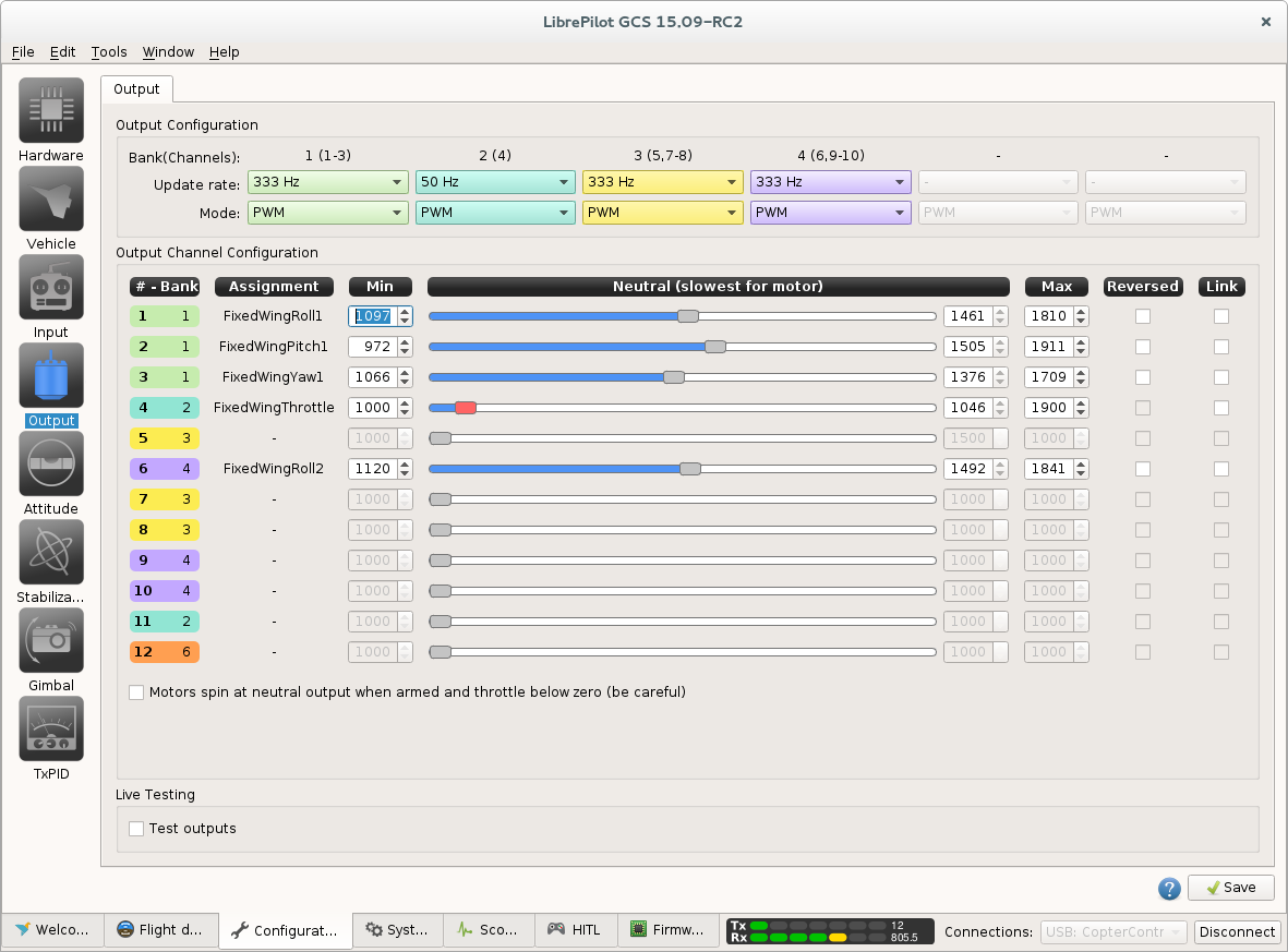
All outputs are organized in Banks, displayed above using colors. This setup should run digital servos (333Hz) and standard Esc (50Hz).
The bank one (Green) cover the outputs channels 1,2,3 and run PWM at 333Hz update rate.
The bank two (Cyan) cover outputs 11 (not used) and output 4 is used for motor with PWM / 50Hz.
The bank three (Yellow) is currently not used but any output mode can be selected for outputs 5, 7 or 8, without interfere with the rest of the system.
Last bank four (Purple) is used for the second aileron servo on output 6 and run PWM at 333Hz update rate.
This example show how outputs / banks need to be selected if you want to setup a custom output mapping.