...
- Standard PWM with configurable rate from 50Hz to 490Hz
- PWMSync (PWM synchronized to the gyro sampling rate)
- OneShot125
Pinout:
PWM Out 6 | PWM Out 5 | PWM Out 4 | PWM Out 3 | PWM Out 2 | PWM Out 1 |
| Vcc | Vcc | Vcc | Vcc | Vcc | Vcc |
| GND | GND | GND | GND | GND | GND |
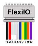
FlexIO Port
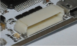
It's primary use is as a receiver port compatible with PWM and PPM receivers, but can also be used to provide up to 6 additional PWM outputs, serial telemetry port, and two GPIO pins.
The connector used is a 10pin JST-HSSH
Pinout:
| Pin | Wire Color | PPM In | PWM In | Telemetry | PWM Out |
|---|---|---|---|---|---|
| 1 | Black | GND | |||
| 2 | Red | Vcc (4,8-15V DC) | |||
| 3 | |||||
| 4 | |||||
| 5 | White | PPM In | PWM In 1 | PWM Out 12 | |
| 6 | Blue | PWM In 2 | PWM Out 7 | ||
| 7 | Yellow | PWM In 3 | Tx | PWM Out 8 | |
| 8 | Green | PWM In 4 | Rx | PWM Out 9 | |
| 9 | Orange | PWM In 5 | PWM Out 10 | ||
| 10 | Violet | PWM In 6 | PWM Out 11 | ||
Main Port
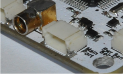
This is a UART serial port with a programmable inverter on the Rx pin. It can be used to connect various serial devices such as GPS receiver, OSD, Telemetry (Bluetooth, OPLink, etc.), S.Bus receiver, DSM satellite receiver...
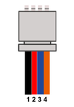
The conector used is a 4pin JST-HSSH.
Pinout:
| Pin | Wire Color | Telemetry | GPS | OSD | DSM | S.Bus |
|---|---|---|---|---|---|---|
| 1 | Black | GND | ||||
| 2 | Red | Vcc (4,8-15V DC) | ||||
| 3 | Blue | Tx | ||||
| 4 | Orange | Rx | DSM In | S.Bus In | ||
| Info |
|---|
The Tx and Rx lines between the controller and device must be connected: Rx to Tx and Tx to Rx. If you connect Rx to Rx and Tx to Tx, serial communication will not work. |
...
The conector used is a 4pin JST-HSSH.
Pinout:
| Pin | Wire Color | Telemetry | GPS | OSD | DSM | SRXL | I2C |
|---|---|---|---|---|---|---|---|
| 1 | Black | GND | |||||
| 2 | Red | Vcc (4,8-15V DC) | |||||
| 3 | Blue | Tx | SCL | ||||
| 4 | Orange | Rx | DSM In | SRXL In | SDA | ||
| Info |
|---|
The Tx and Rx lines between the controller and device must be connected: Rx to Tx and Tx to Rx. If you connect Rx to Rx and Tx to Tx, serial communication will not work. |
...
The conector used is a 4pin JST-HSSH.
Pinout:
| Pin | Analog In | |
|---|---|---|
| 1 | GND | |
| 2 | Vcc | |
| 3 | ADC 0 | |
| 4 | ADC 1 |
Antenna Connector
433MHz antenna for the integrated modem should be connected here.
...
This port is used by developers for flashing and debuging the firmware. Most users will never have to use it.
Pinout:
| Pnn | Function |
|---|---|
| 1 | GND |
| 2 | NRST |
| 3 | SWDIO |
| 4 | SWDCLK |