...
| Section |
|---|
| Column |
|---|
| Go to Configuration > Input > Flight Mode Switch Settings
In this example we have set one flight mode using Attitude stabilization: - Stabilized1 is affected to flight mode position 1 and uses Bank1 (default rates).
|
| Column |
|---|
| 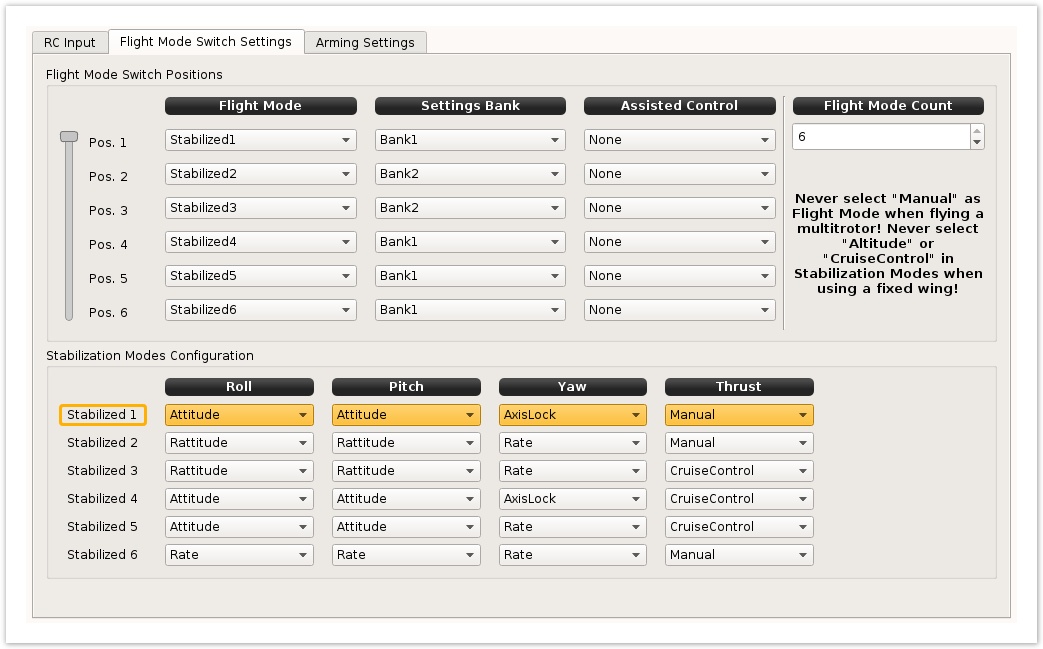 Image Removed Image Removed
|
|
...
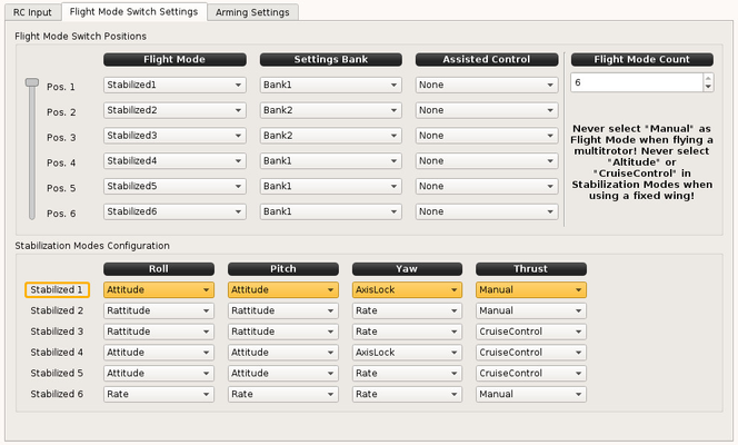 Image Added Image Added
|
|
...
| Section |
|---|
Control structureHere is a simplified basic diagram that show control structure: 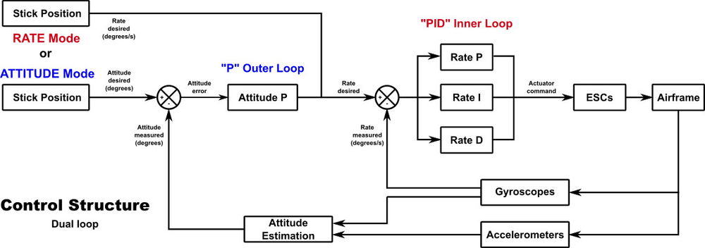
The Attitude stabilization loop (the outer loop) compares the bank angle of an axis with the Attitude desired (stick position) from your transmitter, and sends a signal to the Rate stabilization loop that is the difference of the two. The Rate stabilization loop (the inner loop) compares the rotation rate measured by the gyroscopes for that axis to a control signal. - If you set the stabilization mode for an axis to Rate, the control signal for the Rate (inner loop) comes directly from the transmitter, bypassing the outer loop.
- If instead you set the stabilization mode for that axis to Attitude, the control signal for the Rate loop comes from the Attitude stabilization loop.
|
...
...
Settings
There is two settings for Attitude mode: the max bank angle and the proportional term, assuming the Rate (inner loop) is already tuned.
| Section |
|---|
| Column |
|---|
| Basic tabTick the "Use basic configuration" checkbox. Responsiveness > Attitude: The max bank angle at full stick. Attitude Stabilization (Outer Loop) > Proportional: This adjusts how much the Attitude mode (outer loop) has authority over stabilization. Too much will make your vehicle oscillate in Attitude Mode, too low and you loose vehicle control in Attitude mode. |
| Column |
|---|
| 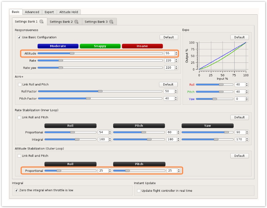 Image Removed Image Removed
|
|
...
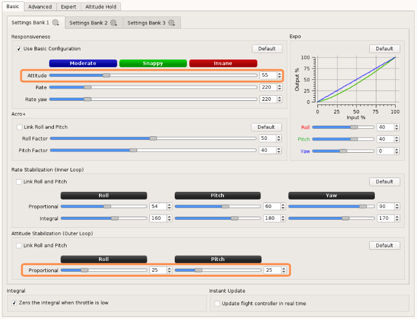 Image Added Image Added
|
|
...
| Section |
|---|
| Column |
|---|
| Advanced tabTick the "Use advanced configuration" checkbox. This advanced tab give more control over settings, now Attitude mode response can be different between Roll and Pitch axis. Attitude mode response: The max bank angle (in degrees) at full stick. Please note the Max rate limit has effect over Attitude mode, in this example this means the vehicle cannot rotate faster than 300deg/s.
Attitude Stabilization (Outer Loop) > Proportional: Same as above, this adjusts how much the Attitude mode (outer loop) has authority over stabilization. Too much will make your vehicle oscillate in Attitude Mode, too low and you loose vehicle control in Attitude mode. Keep Integral value set to 0. |
| Column |
|---|
| 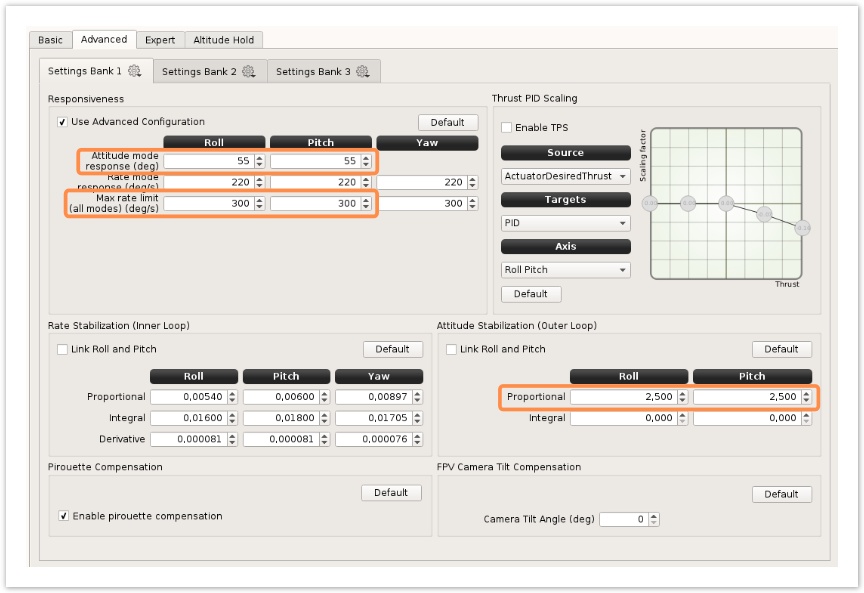 Image Removed Image Removed
|
|
...
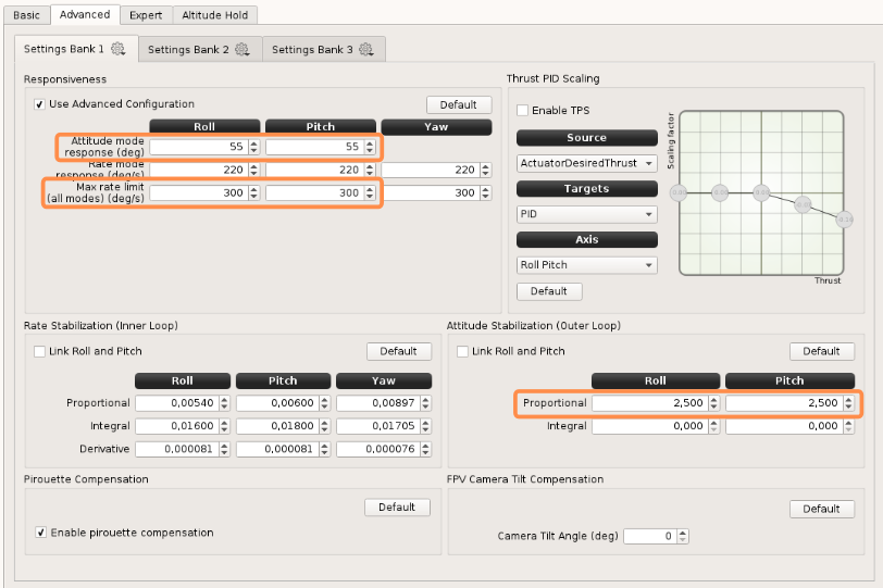 Image Added Image Added
|
|
...