...
| Section |
|---|
Building a SWD cable| Column |
|---|
| | Column |
|---|
| 
|
| Column |
|---|
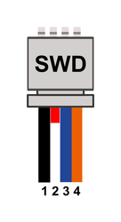
| SWD port pinout | # | Function |
|---|
| 1 | GND | | 2 | NONE | | 3 | IO | | 4 | CLK |
|
Connect the GND, IO and CLK wires between the SWD port and the STLink dongle, the pin2 is not used. | Warning |
|---|
| Please note the IO and CLK lines are inverted for Sparky2 board ! pin3 is CLK and pin4 is IO |
|
| Column |
|---|
|  Image Removed Image Removed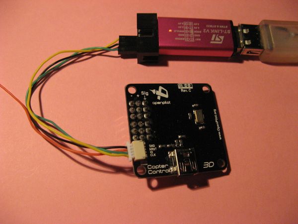 Image Added Image Added
|
|
...
Software setup
...
For bu_* files to be flashed using GCS, see the Downloads page instead.
| Section |
|---|
| Column |
|---|
| Flash Bootloader with STLink Utility
Connect and apply power - Connect the STLink dongle to a USB port.
- Connect the JST connector to the board's SWD port.
- Power the board: can be using external +5V on Output connector, or using the USB port
|
| Column |
|---|
| 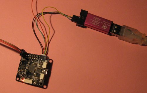 Image Removed Image Removed Image Added Image Added |
|
- Connect the device using the
 icon
icon
...