External arming led for CC3D
Sometimes it is difficult to determine the arming state from the blinking of the internal LED.
In this case, you can attach an external LED.
Configuration
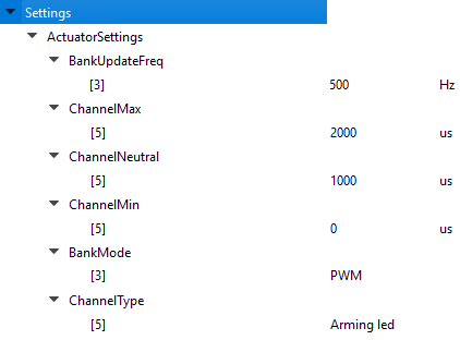
Configure one output channel (in the image, it is pin [5], which is the 6th pin on the CC3D) with the values above.
Be sure to configure the correct bank for the BankUpdateFreq setting and the BankMode setting for the chosen channel/pin.
You can see which channel corresponds to which bank on the configuration output page of the GCS.
Hardware
You cannot drive the external LED directly, you need to have it triggered. The following curcuit uses a MOSFET to trigger the LED voltage.
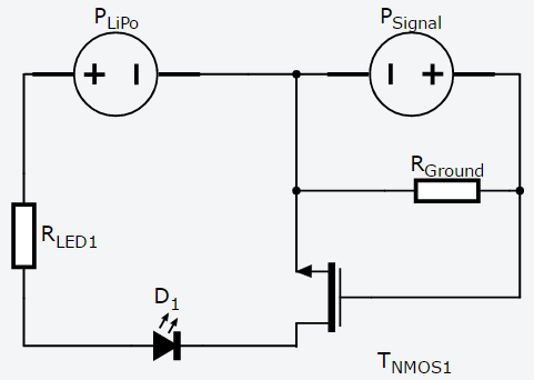
When using an LED board like this one, the RLED1 resistor is usually already on the board.If you are using a single LED, you have to calculate the size of the resistor by yourself.
The RGROUND resistor should be 10k Ω. As a MOSFET, you can use a 2N7000 transistor. This configuration works for a 3S LiPo (max 12.6V).

Example for the worst possible hardware implementation.
Result
This configuration will blink once every few seconds while disarmed, and twice while armed.
Related articles