...
| Description | Board supported | Analog inputs | Firmware file |
|---|
All analog inputs connected to OSD board. RSSI, Vbat, Current. MinimOSD or Micro KV Team Needed for CC3D who can't support current sensor. |
All boards | yes Rssi, Vbat, Current |
|
Nothing connected to OSD hardware, all information comes from flight controller. RSSI information comes from link quality UAVO. Voltage/current sensor can be connected to Revolution board, See Configure a Current-Voltage sensor |
Revo only |
No | |
Same as above Voltage/current sensor connected to Revo + analog RSSI connected to OSD. |
Revo only |
RSSI | |
The config tool used for OSD configuration : ConfigTool_minOPOSD.zip
...
MinopOSD source code is here.
...
| Section |
|---|
| Column |
|---|
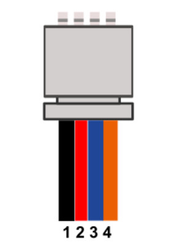
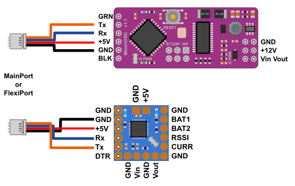
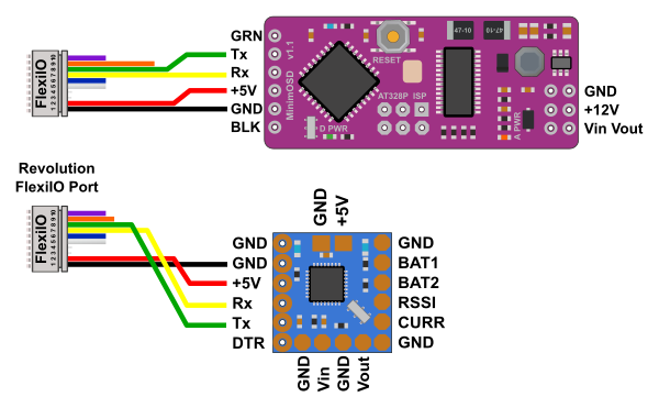
| All boardsCommunication between flight controller and OSD is done using a serial telemetry at 57600bauds. JST connector Main / Flexi port | Connector pin (board) | Description | MinimOSD |
|---|
| 1 | GND | GND | | 2 | VCC | +5V | | 3 | Tx | Rx | | 4 | Rx | Tx |
Please note Tx/Rx lines are crossed
Configure one port with telemetry at 57600bauds, can be MainPort or FlexiPort.
|
| Column |
|---|
| 

|
|
...
| Section |
|---|
| Column |
|---|
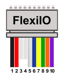
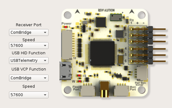
| | Revolution board can provide extra telemetry on FlexiIO port (receiver port), for normal operation no need the DTR pin wired.
JST connector Revolution FlexiIO | Connector pin (board) | Description | MinimOSD |
|---|
| 1 | GND | GND | | 2 | VCC | +5V | | 7 | Tx | Rx | | 8 | Rx | Tx | | 9 (for programming) | DTR | GRN or DTR |
Two options are available for telemetry output on FlexiIO (receiver) port: TELEMETRY or PPM+TELEMETRY |
| Column |
|---|
|
 |
|
...
| Section |
|---|
| Column |
|---|
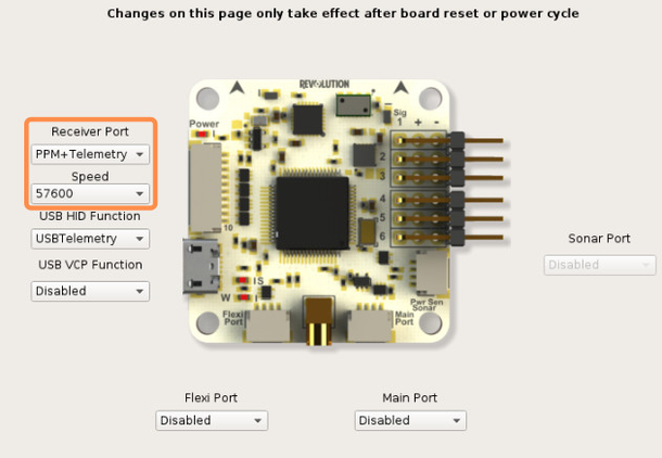
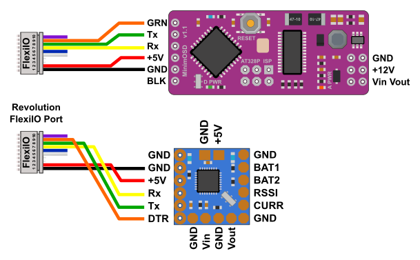
| Using Revolution boardWith the Revolution board you can use the FlexiIO port for telemetry and optional DTR pin is wired with MinimOSD. Please note the programming cannot be done without DTR pin wired. First you need to setup Revolution board as follows : 1 - Connect Revolution board to the computer 2 - Go to the Configuration Tab and Hardware tab 3 - For USB VCP function, select ComBridge
4 - In Receiver Port, select ComBridge 5 - Save and reboot board
Now you can connect the receiver port with the minimOSD board, be sure the revolution board is powered with 5V |
| Column |
|---|
| 
|
|
...
| Section |
|---|
| Column |
|---|
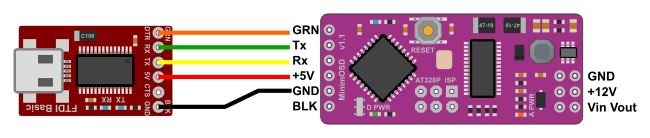
| | Connect FTDI device with MinimOSD as follow |
| Column |
|---|
| 
|
|
...
There is two chips on MinimOSD board, one is a Atmel 368P and the other is a MAX7456 (video chip)
Download and extract archive: ConfigTool_minOPOSD.zip
This is a standalone application and so doesn't require further installation.
...