Work in progress
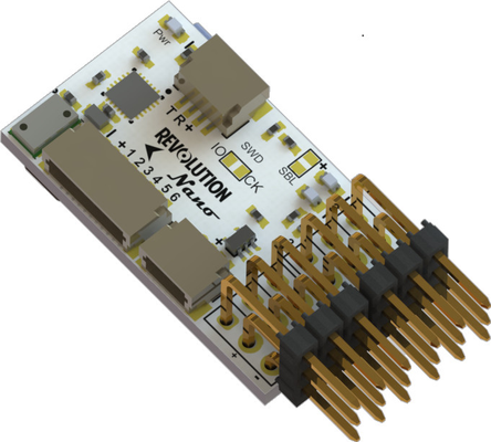
The OpenPilot Revolution Nano is a trimmed down version of the Revolution whit with an updated 10DoF sensor suite.
...
- Invensense MPU9250 3 axis digital MEMS Gyro, Accelerometer and Magnetometer on a single chip
- Measurement Specialties MS5611 barometer
...
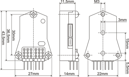
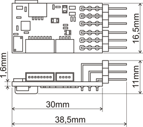
Dimensions
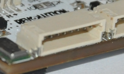
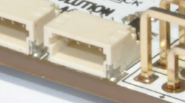
Connectivity
There are several input and output ports availibleavailable.
Powering the board
Board can be powered with 4,8-15V DC power supply, usually from one of ESCs integrated BECs or an external 5V BEC. The voltage used to power the board will also power any peripheral devices like GPS, Bluetooth modem,... connected to it.
...
- Standard PWM with configurable rate from 50Hz to 490Hz
- PWMSync (PWM synchronized to the gyro sampling rate)
- OneShot125
Pinout:
PWM Out 6 (Analog In ADC5) | PWM Out 5 (Analog In ADC6) | PWM Out 4 | PWM Out 3 | PWM Out 2 | PWM Out 1 |
| Vcc | Vcc | Vcc | Vcc | Vcc | Vcc |
| GND | GND | GND | GND | GND | GND |
...
FlexIO
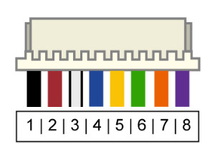
Primarily used as the receiver port supporting PWM and PPM receivers but can also be used as up to 6 additional PWM outputs and analog inputs.
The connector used is an 8pin JST-HSSH.
Pinout:
| Pin | Wire Color | PWM In | PPM In | PWM Out | Analog In |
|---|
| 1 | Black | GND | ||||
| 2 | Red | Vcc (4,8-15V DC) | ||||
| 3 | White | Channel 1 | ||||
| PWM Output 7 | |||
| 4 | Blue | Channel 2 | PPM Sum |
| PWM Out 12 (note 1) | ADC 0 |
| 5 | Yellow | Channel 3 |
| PWM Out 8 (note 2) | ADC 1 |
| 6 | Green | Channel 4 |
| PWM Out 9 (note 2) | ADC 2 |
| 7 | Orange | Channel 5 |
| PWM Out 10 (note 2) | ADC 3 |
| 8 | Violet | Channel 6 |
| PWM Out 11 | ADC 4 |
note 1: Not available if PPM is enabled
note 2: This pin can only work in PWM mode if PPM input is enabled
Main Port
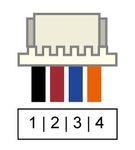
This is a UART serial port with a programmable inverter on the Rx pin. It can be used to connect various serial devices such as GPS receiver, OSD, Telemetry (Bluetooth, OPLink, etc.), S.Bus receiver, DSM satellite receiver...
The conector connector used is a 4pin JST-HSSH.
Pinout:
| Pin | Wire Color | Telemetry | GPS | OSD | DSM | S.Bus |
|---|---|---|---|---|---|---|
| 1 | Black | GND | ||||
| 2 | Red | Vcc (4,8-15V DC) | ||||
| 3 | Blue | Tx | ||||
| 4 | Orange | Rx | DSM In | S.Bus In | ||
| Note |
|---|
The Tx and Rx lines between the controller and device must be connected: Rx to Tx and Tx to Rx. If you connect Rx to Rx and Tx to Tx, serial communication will not work. |
...
This port can support both UART and I2C serial devices, such as external I2C sensors (external magnetometer), GPS, OSD, Telemetry, DSM receiver, SRXL receiver,...
The conector connector used is a 4pin JST-HSSH.
Pinout:
| Pin | Wire Color | Telemetry | GPS | OSD | DSM | SRXL | I2C |
|---|---|---|---|---|---|---|---|
| 1 | Black | GND | |||||
| 2 | Red | Vcc (4,8-15V DC) | |||||
| 3 | Blue | Tx | |||||
| SCL | |||||||
| 4 | Orange | Rx | DSM In | SRXL In | SDA | ||
| Note |
|---|
The Tx and Rx lines between the controller and device must be connected: Rx to Tx and Tx to Rx. If you connect Rx to Rx and Tx to Tx, serial communication will not work. |
...
The VCP can be used for telemetry, debug console and CommBridge ComBridge functionality which binds Main or Flexi port to be used as a comm com port from your PC (useful for configuring your OSD without needing to rip it out of your airframe)
...
Serial Wire Debug port can be used by developers to flash and debug firmware on the STM32F4 microcontroller micro-controller using something like a STM32 Discovery board or ST-Link programmer.
...