
Module Control
By default, the module is not enabled to "save memory" on CopterControl. If you want to use the module, the first thing you need to do is enable it.
Click the checkbox to Enable TxPID module, then click Save to store your option, pause, and power cycle the board.
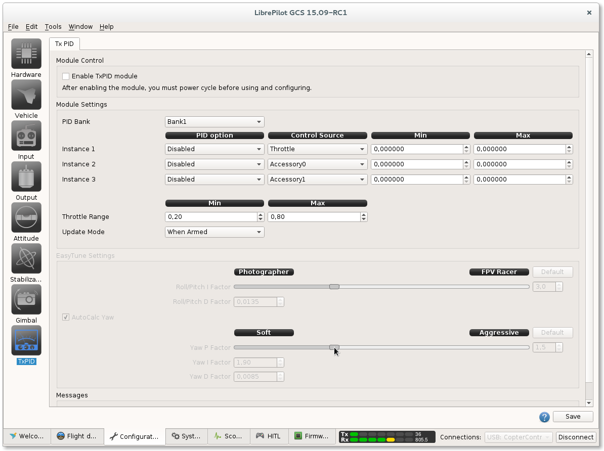
Module Settings
You can adjust a maximum of 3 independent instances. Each instance can control a stabilization value based on a transmitter input.
| Panel | ||
|---|---|---|
| ||
PID optionThis is the stabilization value you want to adjust. The rate values are mapped to the Rate Stabilization Coefficients (Inner Loop)
Control SourceThe Control Source is the transmitter input used with this instance. It can be one of the accessory channels or the throttle channel.
Minimum and MaximumThe Min. and Max. values specify the range where the Control Source can operate. It is advised to carefully select the minimum and maximum values of the range that you map your control to. If your maximum value is set incorrectly, then the slightest change of your control channel may have a huge impact on the stabilization value.
Throttle RangeWhen the throttle is used as a Control Source, then the minimum and maximum can be bound to a specific range of the throttle channel. The default values are 0.2 as Min. and 0.8 as Max. The throttle signal range from the transmitter is mapped to a 0 to 1 range, meaning that the PID value will only be changed if you move the throttle between 0.2 and 0.8 (or actually between 20% and 80%) of your TX throttle range. Update ModeThe setting of the update mode defines how the module updates the values.
|
| Info |
|---|
Note that none of the stabilization values on the Stabilization page can be manually updated in the GCS if the TxPID module is actively updating! Even if you selected other PID values in the module, you cannot update other stabilization values in the GCS. An easy workaround is to set the Update Mode to When Armed. This allows you to update the other stabilization values through the GCS if the board is not armed. |
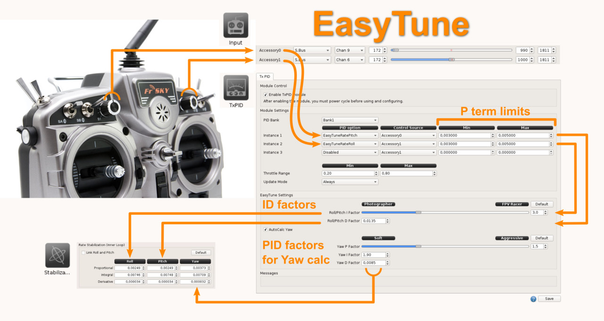
EasyTune logic
EasyTune allow full Pitch/Roll/Yaw PIDs settings using only two potentiometers on RC transmitter.
Easytune video
Widget Connector width 900 url https://www.youtube.com/watch?v=6-CBHgDUF8A height 500
Other example
In the following example we will control the Kp value from the roll rate stabilization on the inner loop.

Suppose we have a transmitter with a variable knob assigned to an aux channel of the receiver. The channel should already be detected and calibrated accordingly on the Input tab. In above example, the channel is bound to Accessory0.
We select the PID option Roll Rate.Kp and assign it to our Accessory0 Control Source. Furthermore, we set the Min of the range on 0.0015 and the Max of the range on 0.0095. This way, the knob on the TX will set the value 0.0015 as Roll Rate.Kp when turned on minimum and 0.0095 when fully turned on maximum.
Saving Values
It is important to note that the adjusted values are not stored permanently onto your board (unless you have changed other values and saved whole object - see below). If you have adjusted the stabilization values via your TX, then you still need to save these to the permanent Flash memory of your board via the the Stabilization tab.
The stabilization values you have been tuning with the TxPID are active on your board as long as the board is not restarted. If you connect the board to the GCS, these values will be loaded and transferred in the Stabilization page. You can now review and save the values permanently.
![]() If the TxPID module was active and you didn't reboot your board, then these updated values are loaded from the board into the GCS. It's important to know that if you want to change and save another value in the Stabilization page you are also saving the values from the TxPID module at this point. The values which were actively controlled by the TxPID module are not permanently stored on the board. But, if you connect the board to the GCS, these values are immediately loaded into the GCS, so you are saving them along with other changes you would make in the Stabilization page. This may sound very normal and logical, but you should remember this when you are adjusting another value in the Stabilization page via the GCS which is not controlled by the TxPID module.
If the TxPID module was active and you didn't reboot your board, then these updated values are loaded from the board into the GCS. It's important to know that if you want to change and save another value in the Stabilization page you are also saving the values from the TxPID module at this point. The values which were actively controlled by the TxPID module are not permanently stored on the board. But, if you connect the board to the GCS, these values are immediately loaded into the GCS, so you are saving them along with other changes you would make in the Stabilization page. This may sound very normal and logical, but you should remember this when you are adjusting another value in the Stabilization page via the GCS which is not controlled by the TxPID module.
| Tip |
|---|
If you are unable to store the values at the field then don't worry. Connect the board to the GCS at a later stage. Activate the module again with your controls on the TX in the last known best position and save your adjustments in the TxPID. If doing so, make sure that the module is actually updating the values. If you have specified that the module should only update when the board is armed, then you must arm your board.
|
Once you have completed your tuning and are no longer using the module, it's advised to disable the TxPID Module. Uncheck Enable TxPID Module, click save and reboot or power cycle your board.
| Section | |||||||||||
|---|---|---|---|---|---|---|---|---|---|---|---|
|
| Expand | ||||||||
|---|---|---|---|---|---|---|---|---|
| ||||||||
This video was created by user Override. |
| Expand | ||
|---|---|---|
| ||
If the control channel of your TX doesn't correspond with the full range you have specified for the PID stabilization value, then most likely the neutral set-point of your control channel isn't set in the middle. If you want a linear output curve of the PID option value you should set the neutral set-point of the control channel in the middle. The neutral set-point can be set in the TxPID. If you don't want to have the average value of the PID option in the middle of the control source, you can shift the neutral point of your control source. |
| Expand | ||
|---|---|---|
| ||
If you want to change other values apart from the ones specified in the TxPID module, make sure that the module is not currently updating the values. You can change the Update Mode to Never or to When Armed and disarm the board to be able to change the other values in the Stabilization Panel via the GCS. |
| Expand | ||
|---|---|---|
| ||
Please make sure that the endpoints of the channel you are using are correctly specified or detected on the Input - Flight Modes - Arming page Input tab. |
| Expand | ||
|---|---|---|
| ||
The GCS will update the values in the Stabilization Panel with the values from your board. If you connect the board to the GCS and want to change some other stabilization values which were not controlled by the TxPID module, then note that the values from the TxPID module were also transferred to the GCS if this module was enabled and active before. Thus, if you click Save, then you are also saving the values from the TxPID module together with the manually adjusted values in the Stabilization Panel. |